


31
[1.1 SIMPLY START]
(SIM-)
Macro configuration parameters
Assignment of the inputs/outputs
(1) To start with integrated Modbus
[Modbus Address]
(Add)
must first be configured, page
196
.
Motor control type
•
[Gen. Use]
(GEn)
macro configuration:
[Motor control type]
(Ctt)
=
[SVC V]
(UUC)
.
• Other macro configurations:
[Motor control type]
(Ctt)
=
[Energy Sav.]
(nLd)
.
Note: These assignments are reinitialized every time the macro configuration changes.
Return to factory settings:
Returning to factory settings with
[Config. source]
(FCSI)
=
[Macro-Conf]
(InI)
page
203
will restore the selected macro configuration.
The
[Macro configuration]
(CFG)
parameter does not change, although
[Customized macro]
(CCFG)
disappears.
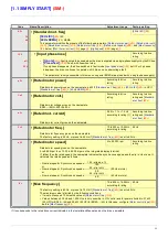
Input/
output
[Start/Stop]
[Gen. Use]
[PID regul.]
[Network C.]
[Pumps.Fans]
AI1
[Ref.1 channel]
[Ref.1 channel]
[Ref.1 channel] (PID
reference)
[Ref.2 channel]
([Ref.1 channel] =
integrated Modbus) (1)
[Ref.1 channel]
AI2
[No]
[Summing ref. 2]
[PID feedback]
[No]
[Ref.1B channel]
AO1
[Motor freq.]
[Motor freq.]
[Motor freq.]
[Motor freq.]
[Motor freq.]
R1
[No drive flt]
[No drive flt]
[No drive flt]
[No drive flt]
[No drive flt]
R2
[No]
[No]
[No]
[No]
[Drv running]
LI1 (2-wire)
[Forward]
[Forward]
[Forward]
[Forward]
[Forward]
LI2 (2-wire)
[Fault reset]
[Reverse]
[Fault reset]
[Fault reset]
[No]
LI3 (2-wire)
[No]
[Jog]
[PID integral reset]
[Ref. 2 switching]
[Ref 1B switching]
LI4 (2-wire)
[No]
[Fault reset]
[2 preset PID ref.]
[Forced local]
[Fault reset]
LI5 (2-wire)
[No]
[Torque limitation]
[4 preset PID ref.]
[No]
[No]
LI6 (2-wire)
[No]
[No]
[No]
[No]
[No]
LI1 (3-wire)
Stop
Stop
Stop
Stop
Stop
LI2 (3-wire)
[Forward]
[Forward]
[Forward]
[Forward]
[Forward]
LI3 (3-wire)
[Fault reset]
[Reverse]
[Fault reset]
[Fault reset]
[No]
LI4 (3-wire)
[No]
[Jog]
[PID integral reset]
[Ref. 2 switching]
[Ref 1B switching]
LI5 (3-wire)
[No]
[Fault reset]
[2 preset PID ref.]
[Forced local]
[Fault reset]
LI6 (3-wire)
[No]
[Torque limitation]
[4 preset PID ref.]
[No]
[No]
Option cards
LI7 to LI14
[No]
[No]
[No]
[No]
[No]
LO1 to LO4
[No]
[No]
[No]
[No]
[No]
R3/R4
[No]
[No]
[No]
[No]
[No]
AI3, AI4
[No]
[No]
[No]
[No]
[No]
RP
[No]
[No]
[No]
[No]
[No]
AO2
[I motor]
[I motor]
[I motor]
[I motor]
[I motor]
AO3
[No]
[No]
[PID Output]
[No]
[No]
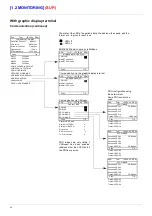
Graphic display terminal keys
F1 key
[No]
[No]
[No]
[No]
[No]
F2, F3 keys
[No]
[No]
[No]
[No]
[No]
F4 key
[T/K]
(Control via graphic
display terminal)
[T/K]
(Control via graphic
display terminal)
[T/K]
(Control via graphic
display terminal)
[T/K]
(Control via graphic
display terminal)
[T/K]
(Control via graphic
display terminal)
In 3-wire control, the assignment of inputs LI1 to LI7 shifts.
Note:
• The factory settings in the parameter tables correspond to
[Macro configuration]
(CFG)
=
[Pumps.Fans]
(PnF)
. This is the
macro configuration set at the factory.
Summary of Contents for ER40-G
Page 2: ......
Page 21: ...21 The display flashes to indicate the presence of a fault ...
Page 241: ......


