


144
[1.7 APPLICATION FUNCT.]
(FUn-)
(1) The parameter can also be accessed in the
[1.3 SETTINGS]
(SEt-)
menu.
(2) If a graphic display terminal is not in use, values greater than 9,999 will be displayed on the 4-digit display with a period mark after the
thousand digit, e.g., 15.65 for 15,650.
Code
Name/Description
Adjustment range
Factory setting
•
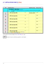
[PID REGULATOR]
(continued)
rIG
• [PID integral gain]
0.01 to 100
1
Integral gain
rdG
• [PID derivative gain]
0.00 to 100
0
Derivative gain
PrP
• [PID ramp]
(1)
0 to 99.9 s
0 s
PID acceleration/deceleration ramp, defined to go from
[Min PID reference]
(PIP1)
to
[Max PID reference]
(PIP2)
and vice versa.
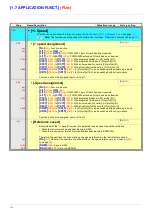
PIC
• [PID correct. reverse]
[No]
(nO)
nO
YES
-
[No]
(nO)
-
[Yes]
(YES)
Reversal of the direction of correction (PIC):
If PIC = nO, the speed of the motor will increase when the error is positive. Example: pressure control with
a compressor.
If PIC = YES, the speed of the motor will decrease when the error is positive. Example: temperature control
using a cooling fan.
POL
• [Min PID output]
(1)
- 500 to 500 or -1,000
to 1,000 Hz according
to rating
0 Hz
Minimum value of regulator output in Hz
POH
• [Max PID output]
(1)
0 to 500 or 1,000 Hz
according to rating
60 Hz
Maximum value of regulator output in Hz
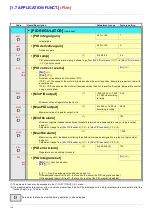
PAL
• [Min fbk alarm]
(1)
100
Minimum regulator feedback monitoring threshold (alarm can be assigned to a relay or a logic output,
page
91
).
Adjustment range from
[Min PID feedback]
(PIF1)
to
[Max PID feedback]
(PIF2)
(2).
PAH
• [Max fbk alarm]
(1)
1,000
Maximum regulator feedback monitoring threshold (alarm can be assigned to a relay or a logic output,
page
91
).
Adjustment range from
[Min PID feedback]
(PIF1)
to
[Max PID feedback]
(PIF2)
(2).
PEr
• [PID error Alarm]
(1)
0 to 65,535 (2)
100
Regulator error monitoring threshold.
PIS
• [PID integral reset]
[No]
(nO)
nO
LI1
-
-
-
-
[No]
(nO)
: Function inactive
-
[LI1]
(LI1)
:
:
-
[...]
(...)
: See the assignment conditions on page
109
.
If the assigned input or bit is at 0, the function is inactive (the PID integral is enabled).
If the assigned input or bit is at 1, the function is active (the PID integral is disabled).
Parameter that can be modified during operation or when stopped.
Summary of Contents for ER40-G
Page 2: ......
Page 21: ...21 The display flashes to indicate the presence of a fault ...
Page 241: ......


