22
4-, 8-, AND 16-PORT SERVSWITCH PS2/USB IP KVM SWITCH
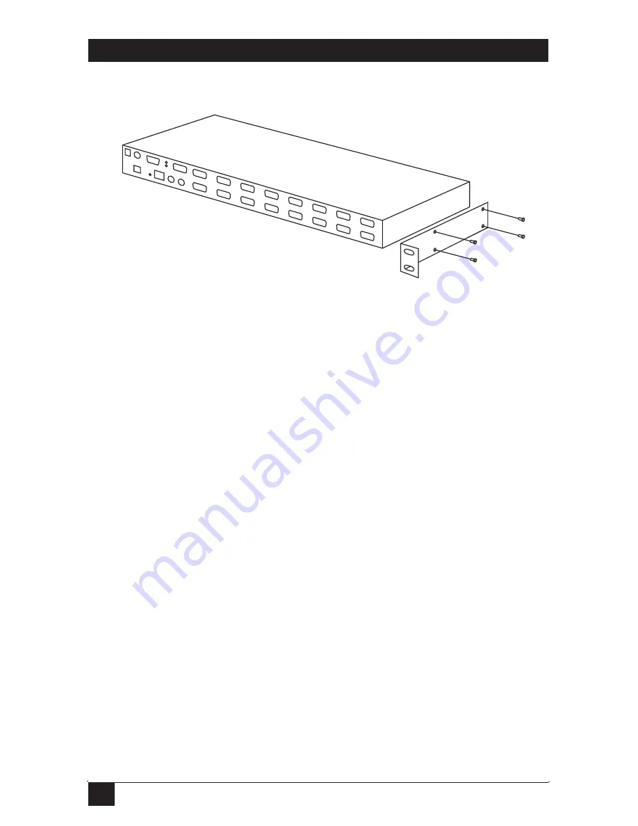
Figure 3-12. Rackmounting the ServSwitch.
3. Connect a straight-through Ethernet patch cable to the LAN port on the
ServSwitch unit’s rear panel.
4. Connect the opposite end of the cable to your network hub, switch, or
terminated wall outlet.
5. If you want to use the ServSwitch as a local console, connect a standard
keyboard and mouse as marked on the ServSwitch unit’s rear panel.
6. Connect a VGA monitor to the video out port on the ServSwitch unit’s rear
panel.
7. If your managed computers (the computers are often servers or critical
systems) have PS/2 connections, attach one end of a 3-in-1 Cable
(EHN70001-0006, EHN70001-0010, EHN9000P-0015, or EHN9000P-0030) to
the computer’s available keyboard, mouse, and VGA out ports. Connect the
opposite end of the cable (with a single HD15 VGA connector) to one of the
PC 1–8 or PC A–H ports on the ServSwitch unit’s rear panel. Repeat this
procedure for each PS/2 enabled managed computer.
8. If your managed computers (the computers are often servers or other critical
systems) have USB connections, attach one end of a 2-in-1 Cable
(EHN9000U-0006, EHN9000U-0010, or EHN9000U-0015) to the computer’s
available USB port and video out port. Connect the opposite end of the cable
(with a single HD15 VGA connector) to one of the PC 1–8 or PC A–H ports
on the ServSwitch unit’s rear panel. Repeat this procedure for each USB-
enabled managed computer.
Summary of Contents for KV9404A
Page 3: ......


