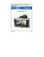
background image

EXTERNAL  HORIZONTAL 

(No  Input  applied) 

Adjust  VERTICAL  GAIN 

ond  CENTERING  to  com­

pletely  fill  the  9rotlcule 

overlay  from  top  to  bottom. 

GROUND 

'scope  V.  INPUT 

to  BASE  jock 

.

!+· 

DO  NOT  READJUST  VERTICAL GAIN 

AFTER  OSCILLOSCOPE  HAS  BEEN  CALIBRATED 

Figure 5.  Oscilloscope Vertical Calibration 

7. Set  the  STEP  SELECTOR  switch  of  the  curve

tracer  to the  .2  volts  per step position.

8. The  display  should  resemble  that  shown  in

Figure  5,  a  series  of  six  vertical  dots,  and  pos­

sibly a light  vertical  trace  between dots.  Adjust

the  vertical  gain  of  the  oscilloscope  so  the  dis­

play  exactly  fills  the  graticule  from  top  to  bot­

tom  (10  divisions).  Adjust  the  vertical  centering

as  required.

9. This  completes  vertical  calibration  of  the  oscil­

loscope.  ONCE  THE  OSCILLOSCOPE  IS  CALI­

BRATED,  DO 

NOT 

READJUST  THE  VERTICAL

GAIN.  During  operation,  vertical  positioning

may be  readjusted  as  required,  but  the  display

must be adjusted to the desired size by controls

on the curve tracer.

Horizontal Calibration 

A horizontal calibration  of 1  volt per division can 

be very accurately obtained using the B (base) jack 

output of the curve tracer when the STEP SELECTOR 

switch is in  the  1  volt per step position. The  voltage 

steps  from  O  to  5  volts  in  5  steps  of  1  volt  each 

(6  steps if  O volts is  counted as  the first step), result­

ing  in  a  series  of  six  horizontal  dots  on  the  oscillo­

scope  screen.  The  horizontal  gain  can  be  adjusted 

so the dots coincide with 5 divisions  of  the graticule. 

This  gives  a  full  scale  value  of  10  volts  which  is 

adequate for testing most small signal transistors. 

Only slightly less accuracy is obtained by adjust­

ing the horizontal gain for two dots per division, thus 

giving  a  full  scale  value  of  20  volts. 

For  higher  test  voltages,  a  less  accurate  (± 15%) 

method of reading the horizontal voltage is available 

by  connecting the sweep voltage output of the curve 

tracer  (H jack)  to  the  horizontal  input of  the  oscillo­

scope.  This  method  will  produce  a  horizontal  trace 

rather than  the  series  of  dots.  The  maximum  sweep 

voltage can be set for any desired  convenient  value, 

such  as  SO  or  100  volts,  as  read  from  the  SWEEP 

VOLTAGE  dial.  The  horizontal  gain  of  the  oscillo­

scope  can  then  be  set  for  a  full  scale  horizontal 

trace  (10  divisions  of  the  graticule.  Each  division 

then equals 10% of the maximum sweep voltage. 

Low Voltage Horizontal Calibration 

(Refer  to  Figure  6) 

1. Complete vertical calibration of the oscilloscope

as  previously  described.

2. Leave the oscilloscope set for external horizontal

input,  and  the  common  ground  connected  be­

tween  the  curve  tracer  and  the  oscilloscope.

3. Disconnect  the  vertical  input  from  the  oscillo­

scope. Ground  the  vertical  input  if  desired.

4. Connect  a  test  lead  from  one  of  the  B  (base)

jacks on the curve tracer to  the  horizontal  input

of  the  oscilloscope.  If  the  left  B  jack  is  used,

the SOCKET switch must be in the LEFT position,

and  if  the  right  B  jack  is  used,  the  SOCKET

switch  must  be  in  the  RIGHT  position.

S. Set  the  STEP  SELECTOR  switch  on  the  curve

tracer  to the  1 

volt  per 

step  position.

6. The  display  should  resemble  that  shown  in

Figure  6,  a  series  of  six  horizontal  dots,  and

possibly  a  light  horizontal  trace  between  dots.

Adjust  the horizontal gain  of  the  oscilloscope so

the  display fills exactly  5 divisions  of  the  grati­

cule. Adjust the horizontal and vertical centering

controls  as  required.

7. This  completes  horizontal  calibration  of  the  os­

cilloscope  at  1  volt  per  division.  ONCE  THE

OSCILLOSCOPE  IS  CALIBRATED,  DO 

NOT

READJUST  THE  HORIZONTAL  GAIN.  During

operation,  horizontal  centering  may  be  read­

justed  as  required.

8. To  calibrate  the  horizontal  display  for  2  volts

per  division,  follow  the  same  procedure  except

adjust the  horizontal  gain for  two  dots  per  divi-

Summary of Contents for 501A

Page 1: ...Model 501A Semiconductor Curve Tracer...

Page 2: ...ave helped provide better and faster service techniques Close contact has been maintained with the manufacturers of consumer products which our test units will be checking and trouble shooting Key per...

Page 3: ...INSTRUCTION MANUAL FOR B K PRECISION MODEL 501A SEMICONDUCTOR CURVE TRACER 8 K DIVISION OF DYNASCAN CORPORATION 1801 W Belle Plaine Avenue Chicago Illinois 60613 Copyright 1972...

Page 4: ...PPLICATIONS 14 Testing Bipolar Transistors 14 NPN vs PNP Transistors 14 CURRENT GAIN MEASUREMENT 14 DC Current Gain DC beta 15 AC Current Gain AC beta 15 Summary of Transistor Current Gain 16 Current...

Page 5: ...4 IC 5 6 7 8 Q 1 Q 2 3 Q 4 Q 5 6 11 12 Q 8 9 10 SW 2 SW 3 SW 4 SW 5 11 72 488 113 9 002 8 DESCRIPTION CAPACITORS B K PART No 1000 fd 35 Volt Electrolytic Capacitor 022 001 9 015 100 fd 25 Volt Electro...

Page 6: ...SJ TEP l OLA l lIt S lfilJC T TO f W f 0 1T N SOC tt SCLtCTOR SET TO lh Hr l OSIHO t I VUtf J 1 S NSITl TV SW l N l TO jl l Ai IV u 01 i t S1 l I IO i G l l G iT SO J tl T Rw t C t I 1 Ill 1S 1 IW 1 4...

Page 7: ...er general purpose oscilloscope is satisfactory as long as it has external horizontal facilities and is DC coupled The B K Models 1440 1460 and 1465 Oscilloscopes are ideal companions for the Model SO...

Page 8: ...7 8 17 16 15 14 13 12 II 10 9 18 0 0 Figure 1 Controls and Operator s Facilities 2...

Page 9: ...rts base to emit ter terminal for measuring collector emitter leakage cur rent with O Volt base bias Selects the gate voltage step value for testing FET s The unit automatically generates gate voltage...

Page 10: ...sitions of the STEP SELECTOR switch constant voltage steps are generated for testing FET s Five selections from 05 to 1 volt per step are offered The polarity of the voltage steps is inverted in relat...

Page 11: ...rent thru the semiconductor being tested and the hori zontal divisions must accurately represent the sweep voltage applied to the semiconductor being tested that is the oscilloscope must be calibrated...

Page 12: ...of reading the horizontal voltage is available by connecting the sweep voltage output of the curve tracer H jack to the horizontal input of the oscillo scope This method will produce a horizontal trac...

Page 13: ...Ground the vertical input if desired Adjust HORIZONTAL GAIN so 4 Connect a test lead from the H jack of the curve tracer to the horizontal input of the oscilloscope 5 Set the SWEEP VOLTAGE control to...

Page 14: ...aneously switched from one semiconductor to the other The SOCKET switch may also be used to start and stop the test of the semiconductor merely activate the empty socket to stop the test This allows c...

Page 15: ...ied for testing zener diodes leakage of signal and rectifier diodes and inverse peak breakdown voltage Forward bias characteristics show voltage drop across the diode junction and resistive or open co...

Page 16: ...t r 3 2ti l p pr t r 1 l 0 2 3 6 7 8 9 10 ADJUST OSCIL LOSCOPE CENTERING CONTROLS TO PLACE START OF ZERO REFERENCE STEP HERE NPN transistors the display should be posi tioned so the curves start at th...

Page 17: ...f the display Increasing the setting widens the display and may cause the display to go off scale Decrease and increase the setting of the control and note the effect upon the display If increasing th...

Page 18: ...s displayed on the VERTICAL SENSITIVITY range being used If the setting is too high some of the curves may reach the current limiting value and be superim posed on each other causing less than five cu...

Page 19: ...ideal for making contact to transistors mounted on P C Boards Refer to the In circuit Probe section for more information When performing in circuit tests use the fast set up markers on the 501 front...

Page 20: ...turn the VERTICAL SENSITIVITY to the 1 mA Div position after each test so that the next test begins with full protection NPN vs PNP Transistors As described previously in the Typical Test section the...

Page 21: ...ent point Simply approx imate the percentage of distance between the curves above and below the poin use it as a percentage of one step to obtain total base current when added to the number of current...

Page 22: ...to gether at higher collector current Each base current step has precisely the same amount of increase which should cause the collector current curves to be separated by equal amounts if the gain wer...

Page 23: ...d does not introduce distortion If 6 10 s are imbalanced distortion will be intro duced due to this non linearity The greater the im balance the greater the distortion The distortion measurement can b...

Page 24: ...would be destroyed by the test Figure 21 shows a typical family of curves with the sweep voltage set high to cause collector break down In the examples shown in the figure break down occurs at a coll...

Page 25: ...t portion of the family of curves in the area of low collector voltage and current below the knee of each curve Notice that the knee of each curve occurs at approximately the same collector voltage re...

Page 26: ...tance The transistor s output impedance or collector resistance is the reciprocal of its output admittance and is measured in ohms It may be calculated by transposing the current and voltage values us...

Page 27: ...collector voltage at various base currents FET curves are a graph of drain current vs drain voltage at various gate voltages FET breakdown voltage may be observed and measured by the same method used...

Page 28: ...e MOS FET s can be damaged by a voltage transient from a static charge carried by the person handling the device Safeguard against such damage and discharge any static charge by touching ground with o...

Page 29: ...ty may be determined by the same method as desribed for transistors if the spacing between curves is equal the FET is linear Pinch Off Vp Voltage Measurement An important characteristic for depletion...

Page 30: ...scale GERMANIUM SILICON 1 100 80 Io ma 0 5 1 1 5 VF volts FORWARD BIAS 2 2 5 When testing diodes only one curve is displayed not a family of curves as displayed for transistors and FET s The forward b...

Page 31: ...OLT j _ _ 2 I I I ZENER I i 1 1 filgl i I i l j i I I I H i_ i t lJ__tH 10 a 6 VR 4 2 o SHARP ZENER KNEE To obtain the most accurate voltage reading pos sible calibrate the full scale oscilloscope hor...

Page 32: ...y The curves C E appear quite close together and careful observation may be required to distinguish the individual curves It may be helpful to spread out the display by in creasing the horizontal sens...

Page 33: ...e Any anode current at anode voltage below the firing point is forward leakage current and can be read directly from the display Reverse Blocking Voltage Reverse blocking voltage is the maximum revers...

Page 34: ...age and increase the de bias supply until the SCR switches on Measure the value of gate voltage at which switching occurred 2 Set the de bias supply to a specified gate volt age and increase the sweep...

Page 35: ...I I 1 Vp t I I I I 10 I 1 i I i 1 L 1 1 I 1 I 5 I i I 1 5 J MA I I l l Ip peak current start of tunnel region Iv valley current end of tunnel region Vp peak voltage start of tunnel region Vv valley v...

Page 36: ...y soldered wires short TP30 TP31 and TP32 to the S Volt line on the PC board 4 Attach a digital voltmeter to TP29 and turn on AC power to the unit 5 Adjust the CALIBRATE pot R36 for a reading of 3 50...

Page 37: ...board It is most important to follow the explicit control setting and set up pro cedure as given in the notes column in order to obtain the illustrated waveforms Point by point sig nal tracing with a...

Page 38: ...VAC 50 IOkl l IG H VOLTAGE ECONO Ut f aiJitllttN1 u nsim R Sl l0ll S 6 SEL CTOR to a countdown chain composed of 3 flip flops within two IC packages IC3 and 4 The second flip flop of IC4 is not used...

Page 39: ...through the SOCKET SELEC TOR to the desired test socket RIGHT or LEFT The higher voltage secondary of the power trans former is full wave rectified by a diode bridge DI through D4 to produce a 120Hz s...

Page 40: ...se new from an authorl r ed B K distributor Our obligation under this warranty is limited to repairing or replacing any product or component which we are satisfied does not conform with the fore going...

Reviews: