


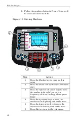

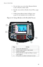
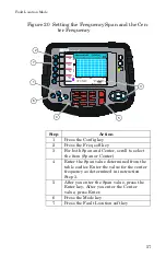

Measure Match Mode
49
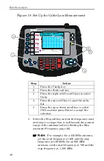
6. Connect a phase stable cable to the Site Analyzer
antenna test port and connect a Cal Combo to the
other end of the cable.
7. Calibrate the Site Analyzer (refer to Calibrate the
Note:
After calibration, with the load still
connected, the output must below -25 dB. If it
is not, there is a problem.
8. Remove the Cal Combo unit from the cable. Do not
disconnect the phase stable cable from the Site
Analyzer.
9. Connect the phase stable cable to one end of the
cable being tested.
10. Connect the Short connection on the Cal Combo
unit to the other end of the cable being tested.
11. Wait at least 10 seconds to allow the trace to
update.
12. Hold the trace that is on the screen (refer to
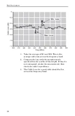
13. Place a triangle-style marker (mark 1) at the
minimum loss point within the frequency band on
the trace (refer to Markers, page 36).
14. Place a triangle-style marker (mark 2) at the
maximum loss point within the frequency band on
the trace.
15. If appropriate, save and label the trace (refer to
Interpreting the Cable Loss Measurement
The graph below shows a typical cable loss measure-
ment. Note that the scale is greatly reduced to show
the cable’s variation across frequency.
Summary of Contents for SITE ANALYZER SA-1700EX
Page 2: ...This page is not blank...
Page 8: ...Bird Site Analyzer vi...
Page 9: ...vii...
Page 30: ...Bird Site Analyzer 16...
Page 142: ...Bird Site Analyzer 128...
Page 148: ...Bird Site Analyzer 134...
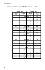
Page 159: ...Maintenance 145 Measured Return Loss dB...
Page 167: ...Maintenance 153 the number of data points you wish measure 238 475 949...


