CANopen Communication
FC5101 and FC5102
50
Version: 2.0
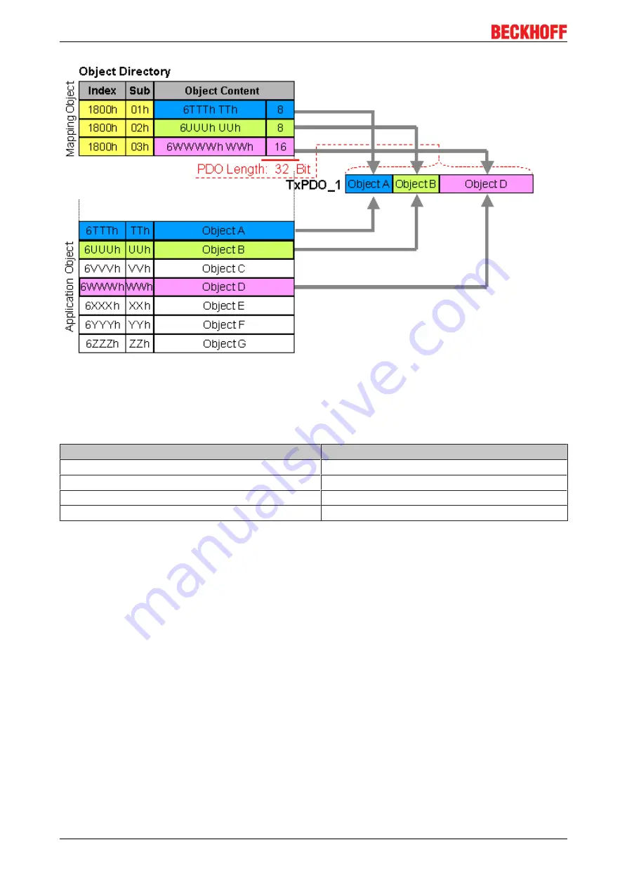
Fig. 42: Mapping representation
Digital and analog input/output modules: Read out the I/O number
The current number of digital and analog inputs and outputs can be determined or verified by reading out the
corresponding application objects in the object directory:
Parameter
Object directory address
Number of digital input bytes
Index 0x6000, sub-index 0
Number of digital output bytes
Index 0x6200, sub-index 0
Number of analog inputs
Index 0x6401, sub-index 0
Number of analog outputs
Index 0x6411, sub-index 0
Variable mapping
As a rule, the default mapping of the process data objects already satisfies the requirements. For special
types of application the mapping can nevertheless be altered: the Beckhoff CANopen Bus Couplers, for
instance, thus support variable mapping, in which the application objects (input and output data) can be
freely allocated to the PDOs. The mapping tables must be configured for this: as from Version 4 of
CANopen, only the following procedure is permitted, and must be followed precisely:
1. First delete the PDO (set 0x1400ff, or 0x1800ff, sub-index 1, bit 31 to "1")
2. Set sub-index 0 in the mapping parameters (0x1600ff or 0x1A00ff) to "0"
3. Change mapping entries (0x1600ff or 0x1A00ff, SI 1..8)
4. Set sub-index 0 in the mapping parameters to the valid value. The device then checks the entries for
consistency.
5. Create PDO by entering the identifier (0x1400ff or 0x1800ff, sub-index 1).
Dummy Mapping
A further feature of CANopen is the mapping of placeholders, or dummy entries. The data type entries stored
in the object directory, which do not themselves have data, are used as placeholders. If such entries are
contained in the mapping table, the corresponding data from the device is not evaluated. In this way, for
instance, a number of drives can be supplied with new set values using a single CAN telegram, or outputs on
a number of nodes can be set simultaneously, even in event-driven mode.


