Product Overview
EP8309-1022
13
Version: 2.0.0
General technical data
Technical Data
EP8309-x022
Special features
Multi-function module
Module electronic supply
from the control voltage Us
Module electronic current consumption
typically 120 mA
Sensor supply
from load voltage Up, DC, any value up to 30 V
Actuator supply
from load voltage Up, DC, any value up to 30 V
Power supply connection
Power supply: 1 x M8 plug, 4-pole
Onward connection: 1 x M8 socket, 4-pole
Process image
Inputs: 2 x 16 bit
Outputs: 2 x 16 bit
Electrical isolation
Control voltage / fieldbus: 500 V
Weight
approx. 165 g
Permissible ambient temperature during operation
-25°C ... +60°C
Permissible ambient temperature during storage
-40°C ... +85°C
Vibration / shock resistance
conforms to EN 60068-2-6 / EN 60068-2-27
EMC immunity / emission
conforms to EN 61000-6-2 / EN 61000-6-4
Protection class
IP65, IP66, IP67 (according to EN 60529)
Installation position
variable
Approvals
CE, cULus
2.4
EP8309 - Process image
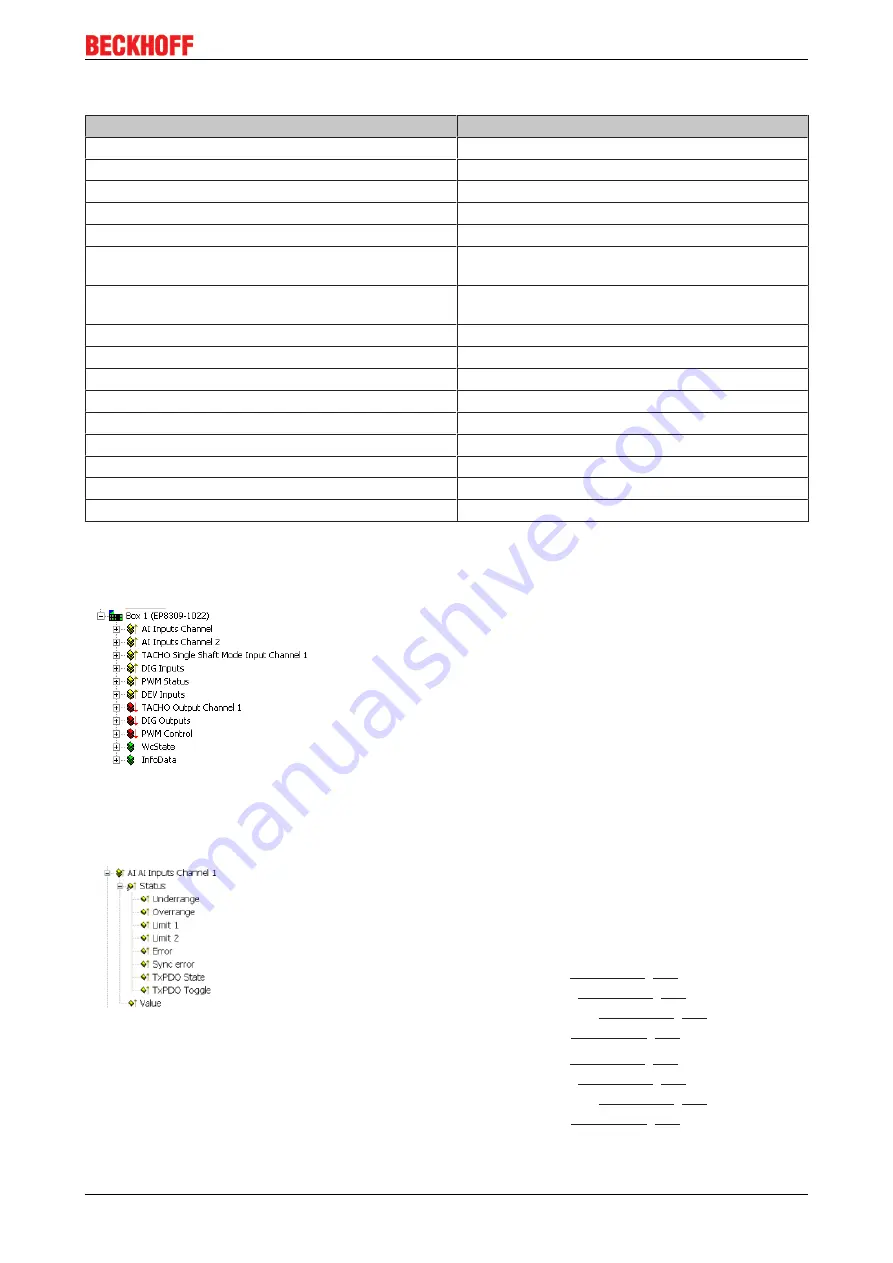
In the default setting the EP8309 is configured for:
• analog input channel 1
• analog input channel 2
• Tacho signal from two sensors on one axis (single-shaft mode)
• 6 digital inputs
• Status of PWM output
• Acknowledge / Reset in the event of a PWM error.
• 6 digital outputs
• General EtherCAT process data
AI Inputs Channel 1 and 2
The data for the first analog channel can be found under
AI Inputs
Channel 1
.
Underrange: Value of the analog input is less than 0/4 mA or -10/0 V
Overrange: Value of the analog input is greater than 20 mA or +10 V
Limit 1: with activated Limit 1 (object
1: value less than limit 1 (set in object
)
2: value greater than limit 1 (set in object
)
3: value equal to limit 1 (set in object
Limit 2: with activated Limit 2 (object
1: value less than limit 2 (set in object
)
2: value greater than limit 2 (set in object
)
3: value equal to limit 2 (set in object
Error: This bit is set if over- or under-range was detected.


