The following image shows the FITC spillover optimally compensated out of the PE parameter.
Once fluorescence compensation has been set for any sample, the compensation setting remains valid for a
subsequent dim or bright sample (provided the signal is not saturated), because compensation subtracts a
percentage of the fluorescence intensity. The following figure illustrates this principle. Although the signals
differ in intensity, the percentage of the FITC spillover into the PE detector remains constant.
About electronics
Introduction
This topic describes the electronics in the BD FACSymphony™ A1 flow cytometer.
Pulse
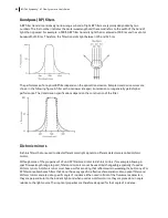
As cells or other particles pass through a focused laser beam, they scatter the laser light and can emit
fluorescence. Because the laser beam is focused on a small spot and particles move rapidly through the flow
cell, the scatter or fluorescence emission signal has a very brief duration—only a few microseconds. This brief
flash of light is converted into an electrical signal by the detectors. The electrical signal is called a pulse. The
following figures illustrate the anatomy of a pulse.
84
BD FACSymphony™ A1 Flow Cytometer User's Guide
Summary of Contents for FACSymphony A1 Flow
Page 1: ...FACSymphony A1 Flow Cytometer User s Guide 23 23437 01 2022 07 For Research Use Only ...
Page 6: ......
Page 10: ...This page intentionally left blank ...
Page 24: ...This page intentionally left blank ...
Page 36: ...This page intentionally left blank ...
Page 50: ...This page intentionally left blank ...
Page 87: ...More information l Running a performance check page 55 Chapter 7 Technical overview 87 ...
Page 88: ...This page intentionally left blank ...
Page 96: ...This page intentionally left blank ...


