Baumer PosCon OXH7 Manual Download Page 36


en_BA_OXH7_PosCon_TCP_IP.docx 

36/98 

Baumer Electric AG 

Friday, June 15, 2018 12:44:11 PM/tof V1.0 ANW_81184815 


Frauenfeld, Switzerland


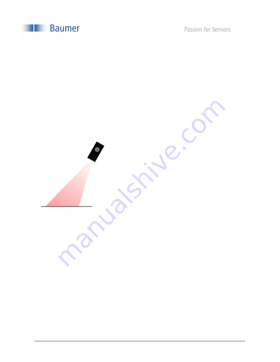
The sensor is aligned with the reference surface. The reference surface must be within the sensor's field of 
view (distance from sensor to reference surface less than distance from sensor to end of measuring range 
Sde). 


Summary of Contents for PosCon OXH7

Page 1: ...Operating instructions PosCon OXH7 smart height measurement ...

Page 2: ...ration via the web interface 21 3 1 The web interface 21 3 2 Monitoring 23 3 3 Parametrization 27 3 4 Device Configuration 50 4 Communication via the process interfaces 52 4 1 Introduction 52 4 2 Modbus TCP 53 4 3 OPC UA 73 5 Operation 86 5 1 Status displays on the sensor 86 5 2 Measuring frequency measuring repeat time and response time 87 5 3 Alarm output 87 5 4 Object to be measured 88 5 5 Memo...

Page 3: ...e and precise measurement 1 1 1 Functional principle of triangulation The sensor works on the laser triangulation principle By means of special optics a laser beam is enlarged into a line and projected to the surface of the object to be measured Using the multi lens system the reflected light from this laser line is projected onto a matrix From this matrix image a controller calculates the distanc...

Page 4: ...tof V1 0 ANW_81184815 Frauenfeld Switzerland 1 1 Safety instructions NOTE Provides helpful operation instructions or other general recommendations ATTENTION Indicates a potentially hazardous situation Avoid these situations in order to prevent any personal injury or damage to the device ...

Page 5: ...W_81184815 Frauenfeld Switzerland 2 Mounting and connections 2 1 Dimensions Optical axis 26 74 85 64 5 M12 x 1 M12 x 1 14 50 7 9 9 4 3 19 4 5 2 21 LED 55 ATTENTION Connection installation and commissioning may only be performed by qualified personnel Protect optical surfaces from moisture and dirt ...

Page 6: ...the sensor is easy to align during installation reference levels have been defined The laser beam of the sensor runs parallel to level R3 and is at a right angle to levels R1 and R2 Levels R1 R2 and R3 serve as a reference for sensor alignment during installation The Left and Right alignment must also be observed 19 mm Level R3 Laser beam Level R1 Level R2 13 mm Left Right ...

Page 7: ...t terms left and right are to be regarded respectively from the viewpoint of the connector side of the sensor End of measuring range Sde X Z Reference point HEIGHT function 0 mm Field of view width The sensor measures the height of objects within the field of view Sde or the optionally teached reference level if Flex Mount is activated is used as the reference surface R2 Width of field of view rig...

Page 8: ...ion The region from the sensor level R2 up to the start of measuring range Sdc is called the blind region i e the sensor cannot detect any objects there If there are any objects in this region this can lead to incorrect measurement values Measuring range Field of view Blind region Object Start of measuring range Sdc End of measuring range Sde R2 ...

Page 9: ...land 2 2 2 Transmitter and receiver axis The transmitter and receiver axes must not be covered by obstacles since this could adversely affect precise measurements Laser beam Measuring range Mr End of measuring range Sde Start of measuring range Sdc 19 mm L1 L2 13 mm Transmitter axis Receiver axis Prohibited area for obstacles ...

Page 10: ...PM tof V1 0 ANW_81184815 Frauenfeld Switzerland 2 2 3 Precise laser alignment with qTarget The field of view is aligned with the housing reference surfaces at the factory The beam position in every sensor is in exactly the same spot which makes planning and sensor replacement very easy ...

Page 11: ... 15 2018 12 44 11 PM tof V1 0 ANW_81184815 Frauenfeld Switzerland 2 3 Mounting The sensor has four mounting holes for flexible alignment and mounting The use of 2 M4x35 screws is recommended for mounting The tightening torque is max 1 2 Nm Tightening torque max 1 2 Nm ...

Page 12: ...se brackets fit the mounting holes of the sensor exactly The sensor can be shifted and adjusted inside the mounting hole Mounting kit for standard installation Order no 11120705 With the mounting bracket for standard installation the sensor can be mounted quickly and easily at a 90 angle to the reference surface Mounting kit 11120705 Contents of this set 90 mounting bracket Threaded plate 2x spher...

Page 13: ... this mounting kit Mounting kit for 30 angled installation with horizontal mounting Order no 11126837 If it is not possible to position the sensor at right angles to the reference surface the sensor can be mounted at an inclination angle of 30 with this mounting kit Mounting kit 11126836 Contents of this set 30 mounting bracket horizontal Threaded plate 2x spherical head screw M4x35 Torx 1x Torx t...

Page 14: ...ion The following points must be satisfied for teaching the reference surface The reference surface must be within the measuring range of the sensor Sdc Sde The sensor may be inclined at a maximum angle of 30 to the reference surface The maximum unevenness of the reference surface 1 must not exceed the maximum value The length of the reference surface must not be less than the minimum reference su...

Page 15: ...ate system is now represented by the M and K axes The height is now measured in the M direction Reference point with inclined installation In the case of angled installation the reference point 0 mm of the K axis shifts out of the center of the field of view or the red visible laser line Due to inclination of the sensor the two field of view sections Width of field of view left and Width of field ...

Page 16: ...safely without any additional safety precautions Nevertheless direct contact between the eye and beam should be avoided ATTENTION The IP protection class is valid only if all connections are connected as described in the technical documentation ATTENTION Connection installation and commissioning may only be performed by qualified personnel ATTENTION Only carry out wiring work when the device is de...

Page 17: ... 4 YE 3 WH 1 Ethernet Color Function Description Pin 1 WH white Tx TX BI_DA Pin 2 BU blue Rx RX BI_DB Pin 3 YE yellow Tx TX BI_DA Pin 4 OG orange Rx RX BI_DB Color Function Description Pin 1 WH white n c Not used Pin 2 BN brown Vs Voltage supply 15 28 VDC Pin 3 GN green n c Not used Pin 4 YE yellow out Switching output push pull Pin 5 GY gray alarm Alarm output push pull Pin 6 PK pink n c Not used...

Page 18: ...length 10 m angled plug Other cable lengths are available M12 4 pin A 4 pin shielded cable is used to transmit the Ethernet signals Baumer connection cables with the following order codes are recommended 11048502 KSG 34A KSG45AP0200G E M12 4 pin to RJ45 length 2 m straight plug 10165276 KSG 34A KSG45AP0500G E M12 4 pin to RJ45 length 5 m straight plug 11051929 KSG 34A KSG45AP1000G E M12 4 pin to R...

Page 19: ... the device If your network does not have a DHCP server you may have to adapt the IP address of your PC With Microsoft Windows 7 proceed as follows 1 Open Start menu Control Panel Network and Internet View network status and tasks Change adapter settings 2 Select your network e g Local Area Connection and then the Properties entry in the context menu 3 Select the Internet Protocol Version 4 TCP IP...

Page 20: ...nd ping OXH7 identifier local Replace identifier either with the eight digit order number or the MAC address indicated on the sensor Example ping OXH7 12345678 local or ping OXH7 11 22 33 44 55 66 local 3 Read the IP address here 192 168 0 250 from the command output Ping is executed for OXH7 12345678 local 192 168 0 250 with 32 bytes of data If you do not gain access to the sensor when you specif...

Page 21: ...rowsers Due to differences in browser technology there may be some differences in appearance between browsers and browser versions or even incompatibilities with the device In our experience these incompatibilities increase with the age of the browser due to a lack of standardization We cannot test all browsers and their various releases so untested browsers may also function with the device Suppo...

Page 22: ...s 2 Commercial name of detected sensor 3 Selection of active parameter setup that is stored in the sensor 4 Setting the configuration or monitoring options 5 Selection of measurement mode 6 Output of measurement value and signal quality over time 7 Overview of active parameters 8 Status of alarm and switching output Alarm Red Active switching output Yellow Active 2 3 1 4 5 6 7 8 ...

Page 23: ... 2 Monitoring Output and evaluation of measurement values 3 2 1 Measurement mode The measurement mode is selected here to define which values are displayed in the Result over Time diagram The mode that is currently selected is indicated by a blue line The yellow icon indicates the active measurement value of the switching output 1 2 ...

Page 24: ...ard deviation is only useful if you consider measurement values which should actually be identical but which vary For the sensor this means that an even surface is observed vertically or with active Flex Mount The standard deviation is then a measure for the unevenness of the surface All measuring points within the preset field of view are taken into consideration Avg HEIGHT Average height of the ...

Page 25: ...eference The plane must cover the entire field of view in the X direction Example This is a profile of 190 points on an even surface as recorded by the sensor before evaluation height in mm It is a typical line The red line represents the mean value and the green lines each represent 1x standard deviation The standard deviation indicates how level the measured line is Standard deviation 0 03 mm Ma...

Page 26: ...spectively Signal quality switching output The colored bar underneath the diagram displays either the signal quality or the switching output This can be set by the user via the button Signal quality Green Valid signal Yellow Weak signal Red No signal no valid measurement value Switching output Yellow Switching output is active high Gray Switching point is inactive low Save Pause Activating Pause f...

Page 27: ...er time Profile or Result over time Camera picture 3 3 1 Result over time profile Result over time As in Monitoring mode the diagram displays the measurement values blue within the adjustable timeframe The gray background and gray line display the switching output window and switching point respectively The colored bar underneath the diagram displays the signal quality or the switching output Gree...

Page 28: ...ly With the tools on the right side the displayed diagram can be saved or analyzed Profile The diagram displays the profile points of the object The field of view is shown in gray Here the field of view can be restricted using the yellow lines these changes take effect immediately Camera picture Output of the unfiltered camera image For example unwanted reflections can be detected and the alignmen...

Page 29: ...plastics or black materials for example 3 3 2 1 2Trigger mode For setting the measuring intervals Free running Measurement with the max possible frequency which may vary depending on the application The sensor measures continuously Interval Measurement cycle with fixed internal interval time in ms The constant measuring frequencies that can be achieved are slower than the non constant frequencies ...

Page 30: ...is on high During the waiting time Hold the power of the laser beam is reduced While Hold is at high all outputs are frozen at their last state To return the sensor to measurement mode Sync In must be set from high to low Sync In must remain on low for at least 5 µs in order for the sensor to begin measuring again Sync In Level Measurement Sync In low 0 2 5 V Run Sync In high 8 V UB operating volt...

Page 31: ...018 12 44 11 PM tof V1 0 ANW_81184815 Frauenfeld Switzerland Measurement in case of Sync In low Every time before a laser pulse is transmitted the sensor checks the level at Sync In If it is low the sensor immediately begins the next measurement Low High Low High Low High ...

Page 32: ...ANW_81184815 Frauenfeld Switzerland Sync In low to high If the Sync In level is on high the sensor always finishes its initiated measurement and then holds off on doing the next measurement All outputs are held hold function 1 ms or 3 ms White black object Hold function Low High Low High Low High ...

Page 33: ...nsor to measurement mode Sync In must be set from high to low Sync In must remain on low for at least 5 µs in order for the sensor to begin measuring again If Sync In switches from high to low level the response time increases in the first measurement cycle by 5 µs 5 µs 1 ms or 3 ms White black object Measurement cycle 2 Measurement cycle 1 Low High Low High Low High ...

Page 34: ...eld of view can be restricted 3 3 2 2 1Mounting assistant The installation conditions can be checked using the mounting assistant The angle of inclination as well as the distance to the reference surface are output The mounting assistant is dependent on the set field of view 3 3 2 2 Right Left Measured angle value in Reference surface Reference axis End of measuring range Sde Distance in mm Exampl...

Page 35: ...urface is even and covers as much of the entire measuring range of the sensor as possible Flex Mount is used if a standard installation right angle to the reference surface or the object is not present the reference surface is closer to the sensor than the end of the measuring range Sde the reference surface is to be automatically teached and or shifted in height the background is to be suppressed...

Page 36: ...8 12 44 11 PM tof V1 0 ANW_81184815 Frauenfeld Switzerland The sensor is aligned with the reference surface The reference surface must be within the sensor s field of view distance from sensor to reference surface less than distance from sensor to end of measuring range Sde ...

Page 37: ...e surface must be within the measuring range 1 Correct distance between sensor and reference surface The inclination angle of the sensor to the reference surface is too large Maximum inclination angle 30 Correct inclination of the sensor The reference surface is too uneven The unevenness must not exceed the max reference surface unevenness 1 Use an auxiliary plate during the teaching process The l...

Page 38: ...unevenness in the reference surface a temporary auxiliary plate can be used for the teaching process This plate should be as flat as possible and must conform to the minimum length of reference surface 1 The plate must be positioned parallel to the reference surface below it The thickness of this plate is not important as long as it is within the field of view of the sensor The thickness of the au...

Page 39: ... reference surface that was originally teached suppressing it and preventing it from having an effect on the measurement result Reset Reset switches off the Flex Mount function If Flex Mount is reset angle 0 and distance end of measuring range Sde1 are set 1 In accordance with chapter Sensor data sheet NOTE As soon as Flex Mount is active the field of view is reset to the maximum field of view NOT...

Page 40: ...view can be individually adjusted The modified field of view need not be symmetrical Even a single limit e g Left Limit can be restricted Right Limit mm Left Limit mm Left Right Right Limit mm Left Limit mm Left Right 90 installation Angled installation Flex Mount NOTE If a reference surface is teached with Flex Mount the reference point of that teached level represents 0 Left Limit and Right Limi...

Page 41: ...15 Frauenfeld Switzerland Set FOV to Max Resets all restrictions of the field of view back to the default settings maximum field of view NOTE If a new reference level is teached with Flex Mount the preset left and right limits are deleted and the modified field of view is reset to the maximum field of view ...

Page 42: ...perated in point mode switch point P1 or in window mode switch point P1 and switch point P2 is defined here Switch point P1 must be larger than switch point P2 The window must be larger than the minimum switching window specified in the data sheet1 3 3 3 1 1Polarity The output level can be inverted with active high or active low here 1 In accordance with chapter Sensor data sheet Switch point P1 S...

Page 43: ... finite list is the measurement with the middle measurement value of a string of numbers e g median of 3 3 5 9 11 is 5 The number of measurement values saved in an array is called the number of measurement values e g 3 3 5 9 11 corresponds to 5 measurement values When a new measurement value is added the oldest is removed moving filter A sudden change in measurement values will only lead to a chan...

Page 44: ...sible that with the moving average the displayed measurement values were never measured as such The measuring frequency is not affected by this filter but the response time is Number of measurement values required until the correct measurement value is displayed When set to High the distance must be stable for 4 16 measurement values before the correct value is displayed When set to Very high the ...

Page 45: ...d and the switch off threshold and is specified as a value in mm Without hysteresis H objects in the border area of the switching point could lead to a toggling of the switching output For reasons of reliability the use of hysteresis is recommended at least as great as the resolution of the sensor The hysteresis can be located before negative hysteresis or after positive hysteresis a switch point ...

Page 46: ... ANW_81184815 Frauenfeld Switzerland Behavior of the switching output for point mode Example Hysteresis positive Example Hysteresis negative High Low Hysteresis Measuremen t value Switch point P1 Level High Low Hysteresis Measuremen t value Switch point P1 Level Level Active low Level Active low ...

Page 47: ...d Behavior of the switching output for Window mode Example Hysteresis positive Example Hysteresis negative High Low Hysteresis Measuremen t value Switch point P1 Level Hysteresis Switch point P2 Window High Low Hysteresis Measuremen t value Switch point P1 Level Hysteresis Switch point P2 Window Level Active high Level Active high ...

Page 48: ...t adjustable The alarm output cannot be adjusted and is output as a push pull signal active high Situation Red LED Alarm output out2 No object inside the measuring range On High Signal gain reached Off Low Signal gain not reached Flashes 8 Hz Low NOTE There is no excess gain hysteresis which is why rapid switching between alarms can occur 3 3 3 4 ...

Page 49: ... the measuring range the sensor will retain the last valid measurement value The alarm output is high during this time Save parameters The parameter changes can be stored in one of three parameter setups in the sensor so that the settings are also available once the sensor has been restarted Unsaved parameters means that changes were made without saving them in one of the parameter setups 3 3 3 5 ...

Page 50: ...0 ANW_81184815 Frauenfeld Switzerland 3 4 Device Configuration The device specific settings are made here 3 4 1 Sensor Info Displays important sensor information such as the serial type serial number and P Code NOTE Note This information should be made available in the event of a service request ...

Page 51: ...activated the sensor synchronizes its internal clock with the defined network time server The time stamps for the measurement values are set based on the synchronization The time basis is UTC Note The daylight saving time functionality is not supported 3 4 4 Process Interface Activate or deactivate the Modbus TCP and OPC UA functionality by toggling the on off button When set to off the sensor no ...

Page 52: ... technology protocols for configuring and retrieving measurement values 4 1 1 Dependencies The sensor supports one client connection for each protocol Read access via the protocols is possible at any time Write access is only permitted once the sensor has been moved to Configuration mode via the respective interface Only one interface can be in Configuration mode at one time The measuring frequenc...

Page 53: ...el The sensor functionality can be accessed by reading or writing entries in the Discrete inputs Input registers and Holding registers tables The following Modbus function codes FC are supported here Read Discrete Inputs FC 02 Read Input Registers FC 04 Read Holding Registers FC 03 Write Single Holding Register FC 06 Write Multiple Holding Registers FC 16 The three tables are independent of one an...

Page 54: ...r 1 55 4 NTP Server 2 100 1 Exposure Time 101 1 Precision 200 8 Field of View 220 1 Set Field of View to MAX 250 1 Reset Flex Mount 251 4 Flex Mount 255 2 Teach Flex Mount 300 11 Switching Output Configuration 400 8 Trigger Mode 410 1 Laser On Off 500 1 Store Setting 501 1 Load Setting 502 1 Reset Setting 503 1 Sensor Reset Address 0 Enter Config Mode Writing any value to this register sets the se...

Page 55: ...does not care which number is written uint16_t Address 2 Session Timeout The Session Timeout is the timeframe after which the sensor automatically leaves the Configuration mode requested via Modbus TCP if no further command has been received in the meantime Function Holding register FUNCTION 03 06 16 Address 2 Length 2 Address Parameter description Data type 2 Session Timeout sec first 2 bytes uin...

Page 56: ...Set Subnet Mask Shadow register for setting the sensor s subnet mask Once this entry has been written the IP address and the standard gateway address can still be set The changes are only activated once the Store Ethernet Parameter command has been executed Function Holding register FUNCTION 03 06 16 Address 15 Length 4 Access Write Only Address Parameter description Data type 15 Subnet Mask Byte ...

Page 57: ...ng any value to this register activates the preset IP configuration Function Holding register FUNCTION 03 06 16 Address 27 Length 1 Access Write Only Address Parameter description Data type 27 Store Ethernet parameters The command does not care which number is written uint16_t Address 32 OPC UA State Function Holding register FUNCTION 03 06 16 Address 32 Length 1 Address Parameter description Data...

Page 58: ...er IP Address Byte 0 uint16_t 52 NTP Server IP Address Byte 1 uint16_t 53 NTP Server IP Address Byte 2 uint16_t 54 NTP Server IP Address Byte 3 uint16_t Address 55 Get NTP Server 2 Function Holding register FUNCTION 03 06 16 Address 55 Length 4 Address Parameter description Data type 55 NTP Server IP Address Byte 0 uint16_t 56 NTP Server IP Address Byte 1 uint16_t 57 NTP Server IP Address Byte 2 u...

Page 59: ...a type 101 Precision Mode 0 Normal 1 High 2 Very High uint16_t Address 200 Field of View Function Holding register FUNCTION 03 06 16 Address 200 Length 8 Address Parameter description Data type 200 201 Left Limit mm float32_t 202 203 Right Limit mm float32_t 204 205 Offset mm float32_t 206 207 Height mm float32_t Address 220 Field of View to MAX Writing any value to this register sets the field of...

Page 60: ...ccess Write Only Address Parameter description Data type 0 Reset Flex Mount The command does not care which number is written uint16_t Address 251 Flex Mount Function Holding register FUNCTION 03 06 16 Address 251 Length 4 Address Parameter description Data type 251 252 Angle deg float32_t 253 254 Distance mm float32_t Address 255 Teach Flex Mount Writing to this register teaches the currently mea...

Page 61: ...ch Mode int32_t 306 307 Hysteresis float32_t 308 309 Measurement Value 0 Average 1 Max 2 Min 3 Delta 4 Standard Deviation int32_t 310 Polarity 0 Active Low 1 Active High uint16_t Address 400 Get Trigger Mode Settings Function Holding register FUNCTION 03 06 16 Address 400 Length 8 Address Parameter description Data type 400 401 Trigger Mode 0 FreeRunning 1 SingleShot 2 Interval 3 Internal not sett...

Page 62: ...nt16_t Address 500 Store Setting Stores the currently active parameters in a parameter setup Function Holding register FUNCTION 03 06 16 Address 500 Length 1 Access Write Only Address Parameter description Data type 500 Parameter Setup No 1 2 or 3 uint16_t Address 501 Load Setting Loads a parameter setup Function Holding register FUNCTION 03 06 16 Address 501 Length 1 Access Write Only Address Par...

Page 63: ...CTION 03 06 16 Address 502 Length 1 Access Write Only Address Parameter description Data type 502 Parameter Setup No 1 2 or 3 uint16_t Address 503 Sensor Reset Function Holding register FUNCTION 03 06 16 Address 503 Length 1 Access Write Only Address Parameter description Data type 503 Sensor Reset command does not care which number is written uint16_t 4 2 3 1 ...

Page 64: ... Setting 1 450 29 Get Setting 2 490 29 Get Setting 3 600 108 Get Block Mode Memory 0 708 108 Get Block Mode Memory 1 816 108 Get Block Mode Memory 2 924 108 Get Block Mode Memory 11 1032 108 Get Block Mode Memory 12 1140 108 Get Block Mode Memory 13 1248 108 Get Block Mode Memory 14 1356 108 Get Block Mode Memory 15 1464 108 Get Block Mode Memory 16 1572 108 Get Block Mode Memory 3 1680 108 Get Bl...

Page 65: ... 40 Length 46 Address Parameter description Data type 40 44 Product ID STRING 9 45 77 Sensor Type STRING 65 78 84 Serial Number STRING 15 Address 90 Frontend Version Returns the version of the website Function Input register FUNCTION 04 Address 90 Length 5 Address Parameter description Data type 90 94 Frontend Version STRING 9 Address 100 Read Eth Config The Ethernet configuration contains the IP ...

Page 66: ...r FUNCTION 04 Address 120 Length 6 Address Parameter description Data type 120 Byte 0 uint16_t 121 Byte 1 uint16_t 122 Byte 2 uint16_t 123 Byte 3 uint16_t 124 Byte 4 uint16_t 125 Byte 5 uint16_t Address 130 Support E Mail E mail address which the web frontend can show as a contact address Function Input register FUNCTION 04 Address 130 Length 16 Address Parameter description Data type 40 55 Suppor...

Page 67: ...2_t Address 180 Flex Mount Limits Returns the limits of the Flex Mount Function Input register FUNCTION 04 Address 180 Length 6 Address Parameter description Data type 180 181 Minimum Distance For a linear movement of the reference system on z axis mm float32_t 182 183 Maximum Distance For a linear movement of the reference system on z axis mm float32_t 184 185 Maximum Rotation Angle This is the m...

Page 68: ...at32_t 207 208 Min mm float32_t 209 210 Delta mm float32_t 211 212 Standard Deviation mm float32_t 213 214 Measurement Rate Hz float32_t 215 216 Time Stamp sec uint32_t 217 218 Time Stamp usec uint32_t Address 250 Get Teachable Range Returns the min max range which the switching points can be set to Function Input register FUNCTION 04 Address 250 Length 14 Address Parameter description Data type 2...

Page 69: ...oat32_t Address 400 Unsaved Config Indicates if the sensor is running with a configuration which is not stored in any setting Function Input register FUNCTION 04 Address 400 Length 1 Address 401 Active Setting Number Returns the number of the active setting The available setting numbers are 1 3 Function Input register FUNCTION 04 Address 401 Length 1 Address 410 Get Setting 1 The sensor supports t...

Page 70: ...t32_t 432 433 Switch Mode int32_t 434 435 Hysteresis Width mm float32_t 436 437 Measurement Value Switching Output int32_t 438 Polarity uint16_t Address 450 Get Setting 2 The sensor supports three settings 1 2 3 which hold an entire configuration These settings can be stored loaded and reset Function Input register FUNCTION 04 Address 450 Length 29 Address Parameter description Data type 450 451 T...

Page 71: ...d an entire configuration These settings can be stored loaded and reset Function Input register FUNCTION 04 Address 490 Length 29 Address Parameter description Data type 490 491 Trigger Mode int32_t 492 493 Fixed Trigger Time us uint32_t 494 Exposure Time us uint16_t 495 Precision uint16_t 496 497 Range Left mm float32_t 498 499 Range Right mm float32_t 500 501 Range Offset mm float32_t 502 503 Ra...

Page 72: ...m here the content can then be retrieved sequentially in multiple sub blocks Each sub block contains six measurement values Function Input register FUNCTION 04 Address 600 708 816 924 1032 1140 1248 1356 1464 1572 1680 1788 1896 2004 2112 2220 2328 Length 108 Address offset Parameter description Data type 0 Quality uint8_t 1 SwitchOut OR AlarmOut SwitchOut 0x0001 AlarmOut 0x0002 0 Nothing 1 Switch...

Page 73: ...rogrammable logic controllers Various software libraries are available for PC based systems Further information is available on the website of the OPC Foundation https opcfoundation org An example of how a freely available OPC UA client can be used is described below 4 3 1 Commissioning with the UaExpert OPC UA Client The UaExpert software described can be acquired from https www unified automatio...

Page 74: ...mer Electric AG Friday June 15 2018 12 44 11 PM tof V1 0 ANW_81184815 Frauenfeld Switzerland Expand Custom Discovery and select Double click to Add Server Enter the IP address of the sensor here and click OK to confirm opc tcp 192 168 0 250 ...

Page 75: ..._OXH7_PosCon_TCP_IP docx 75 98 Baumer Electric AG Friday June 15 2018 12 44 11 PM tof V1 0 ANW_81184815 Frauenfeld Switzerland The sensor appears with the IP address Click OK to confirm opc tcp 192 168 0 250 ...

Page 76: ...is now connected and can be used The function tree was read from the sensor and is displayed in the left hand window under Address Space Explanation of symbols Nodal point Variable node partly read write Variable node property Method node action with call Making settings As soon as InitLock has been activated settings can be made on the sensor Example The precision should be set to Standard measur...

Page 77: ...P docx 77 98 Baumer Electric AG Friday June 15 2018 12 44 11 PM tof V1 0 ANW_81184815 Frauenfeld Switzerland The value can now be set under Value Double click on this and change Double click and adjust using the dropdown menu ...

Page 78: ...nfeld Switzerland Reading measurement values Under Measurement MeasurementValues Click on the required measurement value here e g Average The Attribute window on the right outputs all relevant values for this property The measurement value is found under Value Clicking Refresh updates the measurement value 4 3 1 5 ...

Page 79: ... 44 11 PM tof V1 0 ANW_81184815 Frauenfeld Switzerland 4 3 2 Structure and description of the OPC UA commands Sensor function tree Unlocking In order to configure the sensor this must be unlocked using a command Right click on InitLock and then execute with Call 4 3 2 1 4 3 2 2 ...

Page 80: ...nt Stored Flex Mount values for angle and distance Precision Precision filtering Settings standard high very high ResetFlexMount Reset Flex Mount to default settings SetFieldOfViewToMax Reset field of view to maximum values SwitchingOutputConfigur ation Make settings for the switching output hysteresis polarity threshold window set switching points TeachFlexMount Activate Flex Mount teach in the n...

Page 81: ...r ModbusTCP Switching on off the Modbus interface by setting 0 Off or 1 On OPC UA command Sensor command ProductId Output of the article order number of the sensor OPC UA command Sensor command BreakLock Not implemented ExitLock Leave Configuration mode InitLock Set sensor to Configuration mode enabling settings to be changed Locked Specifies whether the sensor is currently in Configuration mode L...

Page 82: ... the delta value Max Output of the maximum value MeasurementRate Output of the measurement rate in Hz Min Output of the minimum value Quality Output of the signal quality 0 Valid signal 1 Low signal 2 No signal StandardDeviation Output of the standard deviation SwitchingOutput Output of switching output active yes no TimelsSynchronized The time stamp of the measurement is based on the time synchro...

Page 83: ... subnet mask and standard gateway StoreParameterSetup Store active parameters in parameter setup 1 3 The value 1 3 must be specified TeachFlexMount Teach Flex Mount The value of the reference thickness can be specified If the conditions for Flex Mount are not met an error is returned and Flex Mount is not activated 50000 Distance not within permitted range 50001 Angle not within permitted range 50...

Page 84: ...t of the last 100 measurement values ModbusActive Modbus on off MountingPosition Mounting assistant current mounting angle and distance to the reference surface NtpServer1 IP address for NTP Network Time Protocol server 1 NtpServer2 IP address for NTP Network Time Protocol server 2 ParameterSetup1 Parameter setup 1 ParameterSetup2 Parameter setup 2 ParameterSetup3 Parameter setup 3 Precision Stand...

Page 85: ... value 1 3 must be specified ResetParameterSetup Delete stored parameter setup 1 3 The value 1 3 must be specified StoreParameterSetup Store active parameters under parameter setup memory location 1 3 The value 1 3 must be specified StoredParameterSetups Display or adjust parameter setups 1 3 UnsavedParameterSetup True if the currently active configuration has not yet been saved in nonvolatile per...

Page 86: ...utput out 2 active No measuring object within the field of view or signal quality is inadequate Signal gain Object close to signal gain or signal quality not ideal Green Power Sensor ready for operation Ethernet connection not available Short circuit Check connection at switching or alarm output Blue Link Ethernet connection established Data transmission Data packets are sent and received via Ethe...

Page 87: ... time is required for dark objects than for light objects The sensor automatically controls the exposure time on the basis of the amount of light reflected by the object This slows down the measuring frequency and the response time In this case the degree of slowdown is dependent on the laser class of the sensor 5 3 Alarm output The alarm signal is output as a push pull signal active high It is se...

Page 88: ...etween incident and reflected light Definition of objects Object white approx 90 reflectivity Object black approx 6 reflectivity Object light 18 reflectivity Object dark 6 18 reflectivity 5 4 3 Standard object The technical data for sensors in the data sheet refers to measurements with a Baumer standard object This standard object is precisely defined in size shape and color making multiple measur...

Page 89: ...98 Baumer Electric AG Friday June 15 2018 12 44 11 PM tof V1 0 ANW_81184815 Frauenfeld Switzerland 5 5 Memory All changes stored in a parameter setup are saved in nonvolatile permanent memory and are even retained after a power outage ...

Page 90: ...ELD OF VIEW The red visible laser beam does not represent the maximum field of view If the object is at the edge of this beam it could be outside the measuring range Move object The object is outside the field of view vertically or is in the blind region of the sensor Unreliable measurement value The measurement value jumps back and forth The object is not in the measuring range Avoid bright objec...

Page 91: ...y a qualified person Installation For mounting use only the mechanical mountings and mechanical mounting accessories intended for this product Unused outputs must not be wired In cable versions with unused cores these cores must be insulated Always comply with admissible cable bending radii Prior to electrical connection of the product the system must be disconnected from the power supply In areas...

Page 92: ...stare into the beam Accidental short term exposure up to 0 25 s does not damage the eye because the corneal reflex can automatically protect the eye sufficiently from longer radiation Class 2 lasers may be used without any further protection if intentional staring into the beam is not required for the application FDA certification plate Information and warning plate PosCon OXH7 OM70 X multi spot F...

Page 93: ... Non compliance with these safety instructions may lead to the release of hazardous laser beams 6 4 Cleaning the sensors The laser distance sensors do not require any maintenance except that the front windows must be kept clean Dust and fingerprints can impair sensor function It is normally sufficient to wipe the windows with a clean soft lens cleaning cloth Alcohol or soapy water can be used in c...

Page 94: ...filter AVG HEIGHT repeat accuracy max field of view width 8 µm 234 without filter 4 µm 2345 with precision high filter 2 µm 2345 with precision very high filter MIN MAX HEIGHT repeat accuracy 16 µm 23 without filter 8 µm 235 with precision high filter 4 µm 235 with precision very high filter Linearity error 20 µm 2346 Temperature drift 0 04 Sde K 234 PRECISION filter values Standard High Very High...

Page 95: ...ent conditions PosCon OXH7 11185166 OXH7 11185166 Ambient light immunity 35 kLux Operating temperature 10 50 C Storage temperature 20 60 C Protection class IP 67 Vibration sinusoidal IEC 60068 2 6 2008 7 5mm p p for f 2 8Hz 2g for f 8 200Hz or 4g for 200 500Hz IEC 60068 2 6 2008 1 5 mm p p at f 10 57 Hz 10 cycles per axis 10 g at f 58 2000 Hz 10 cycles per axis Resonance test IEC 60068 2 6 2008 1 ...

Page 96: ...tical focused toward laser line Focal distance df 125 mm Beam size at window Vertical Parallel 2 5 mm 7 5 mm Beam size at focal point Vertical Parallel 0 1 mm L 73 mm Beam divergence Vertical δ Parallel δ 16 0 mrad 30 2 Nominal ocular hazard distance NOHD 1 NA Laser classification as per IEC 60825 1 2014 Laser class 1 1 Outside the Nominal ocular hazard distance the radiation exposure is below the...

Page 97: ...en_BA_OXH7_PosCon_TCP_IP docx 97 98 Baumer Electric AG Friday June 15 2018 12 44 11 PM tof V1 0 ANW_81184815 Frauenfeld Switzerland 8 Revision history 06 15 2018 tof Manual released in version 1 0 ...

Page 98: ...en_BA_OXH7_PosCon_TCP_IP docx 98 98 Baumer Electric AG Friday June 15 2018 12 44 11 PM tof V1 0 ANW_81184815 Frauenfeld Switzerland ...

Reviews: