background image

8‐11


9. Function Codes 

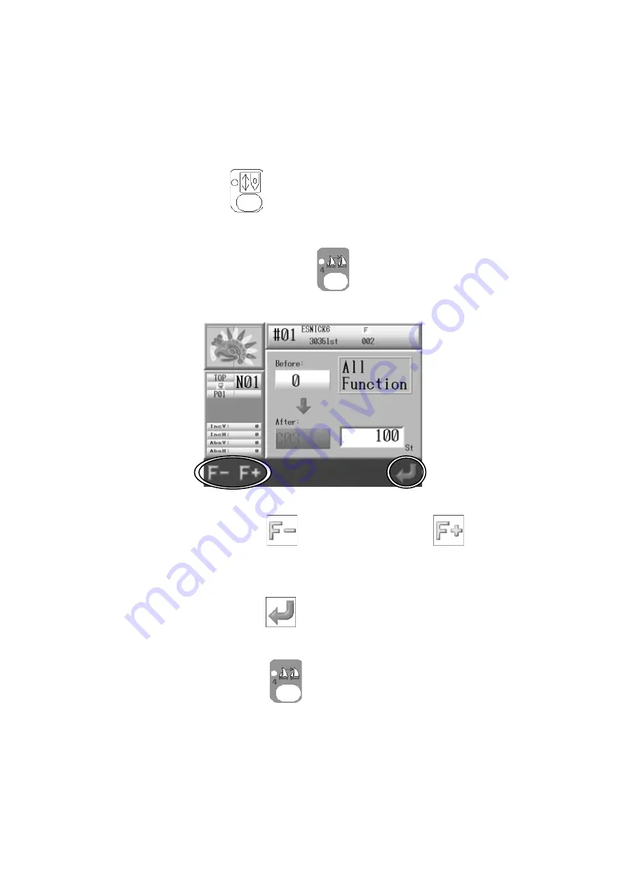
Instructions on changing all function codes while the machine is sewing 
Use this feature with the High Speed Float (By Stitch Count) to change the Function code of 
the desired stitch. *Refer to 

Chapter 13  1. Function Codes

 for the details of the Function 

codes.  


1. Press the 

Drive Key 

  and the Drive mode screen appears. 

2.  Float to the desired stitch number you want to insert or change a function code on. 

3.  Press and hold the Color Change key


  for 2 short beeps.   

4.  The Function Code screen appears. 


5. Press the A-key  below the 

 icon


or  B-key below the 

  icon  to  change  the 

Function code. 


6. Press the G-key below the 

 icon to update the Memory with the new Function 

Code. 

Press the Color Change key 


again to finish. 


Summary of Contents for BEXS

Page 1: ...B E X S Instruction Manual ...

Page 2: ...1 Appearance and Components 3 2 2 Panel Switches 3 6 3 Powering the Machine On Off 3 8 4 Origin Set 3 9 5 Screen Structure 3 10 6 Information Screen 3 11 7 Design List Display Settings 3 13 8 Stand By and Drive Mode 3 15 9 Switching Screens 3 16 10 Numeric Entry Dialogue Box 3 18 11 Character Entry Dialogue Box 3 19 12 Confirmation Message 3 20 13 Error Messages 3 21 Chapter 4 Manual Operations 4 ...

Page 3: ...Loading Saving Designs 5 1 1 Before Loading Downloading Designs 5 2 2 Before Using a USB Flash Drive 5 4 3 Loading Designs from a USB Flash Drive 5 7 4 Saving Designs to a USB Flash Drive 5 12 5 USB Administration 5 15 6 ABC Drive 5 20 7 Loading Thorough the COM port 5 21 8 Saving Through the COM port 5 24 Chapter 6 Memory Designs 6 1 1 Selecting a Design 6 2 2 Design Information 6 3 3 Changing De...

Page 4: ...Up 7 11 Chapter 8 Embroidery 8 1 1 Start Point 8 2 2 Drive Mode 8 3 3 Speed 8 4 4 Trace 8 5 5 Float 8 7 6 High Speed Float By Stitch Count 8 8 7 High Speed Float By Color Change 8 9 8 Color Code Change Teaching 8 10 9 Function Codes 8 11 10 Stitch Back 8 12 11 Automending 8 13 12 Stand By Mode Resume 8 14 Chapter 9 Network 9 1 1 Before Using the Network System 9 2 2 Registering the Operator Code 9...

Page 5: ...tch Processor 10 6 Chapter 11 Preference 11 1 1 Changing Machine Conditions MC 11 2 2 MC List 11 4 3 Sequin Adjusting Mode 11 13 4 Setting the Screen Color 11 14 5 Setting the Design Color 11 17 6 Network 11 20 7 Date Setting 11 22 8 Software Version 11 23 Chapter 12 System 12 1 1 System Structuring 12 2 2 System Software Update 12 3 3 Initializing Memory 12 5 Chapter 13 Appendix 13 1 1 Function C...

Page 6: ...1 1 Chapter 1 Safety Instructions This chapter contains information on the following 1 Important Safety Instructions 2 Grounding Instructions 3 Warning Labels ...

Page 7: ...ad this manual thoroughly and follow all instructions The icons in the manual show the importance of the contents Acknowledge the following descriptions beforehand Icons Warning Caution Safety information about protecting yourself Safety information about protecting the machine ...

Page 8: ...starting the machine be sure nobody is near the machine Keep children away from the machine while operating Follow the electrical specifications instructed Do not modify or dismantle the machine It can cause fire or malfunction Connect this embroidery machine to a properly grounded outlet only Do not use the machine in the humid area It can cause a fire or electrical shock Do not damage modify pul...

Page 9: ...the machine with any air openings blocked Keep ventilation openings of the machine free from the accumulation of lint dust and loose cloth Unplug the power cable before servicing to the controller Residual power may cause electric shock Wait for more than 4 minutes before opening the cover Some parts in the controller can be very hot Be sure not to burn your hands Use only attachment and parts rec...

Page 10: ...ny or the law Danger Not grounding the machine may cause electrical shock 2 Ask for a service call if the power connection is not clearly understood 3 Do not use adaptor to the power plug Ask for a service call to connect the machine to another power source 4 Ask for a service from the power company to check the connection from the ground to the power outlet Check the voltage and capacity of the p...

Page 11: ...1 6 3 Warning labels Give attention during operation to the parts labeled Warning Labels Contents Needle Hazard Warning Label Hair Warning Label Take Up Lever Warning Label Frame Warning Label ...

Page 12: ...1 7 Warning Labels Contents Hook Warning Label Belt Warning Label ...

Page 13: ...2 1 Chapter 2 Introduction This chapter contains information on the following 1 Specifications 2 Features ...

Page 14: ...0 RH No condensation allowed 6 Grounding Grounding resistance to be less than 100Ohm Type 3 grounding 7 Trimmer Compatible Mark 4 5 6 8 Thread Break Detection 9 USB Ports USB2 0 Front 1 port Back 2 ports 10 Network system 100BASE 10BASE 11 Emergency Stop Switch Some models do not apply 12 Option Cap frames For Cylinder machines Sequin device Automatic Lubrication system Twin Sequin device Light Cu...

Page 15: ...wed and reported from the server computer 4 Large Memory Capacity The memory capacity is 10 million stitches with 100 memory locations 5 High Speed Drive The microcomputer automatically chooses the most efficient speed in 10 rpm increments Max Speed may vary for each model 6 Quiet Drive Inverter driven main motor allows powerful and quiet drive It also allows accurate speed control and stop positi...

Page 16: ... the appliqués to the garments This can also be used for replacing frames at the end of sewing 12 Socks Automatic design conversion for socks 13 Matrix Embroidery Automatic layout for the Matrix embroidery Easy setting can create a repetition design 14 The registration of the start position The controller automatically saves the last start position of designs in memory When you go to sew a design ...

Page 17: ...d Components 2 Panel Switches 3 Powering the Machine On Off 4 Origin Set 5 Screen Structure 6 Information Screen 7 Design List Display Settings 8 Stand By and Drive Mode 9 Switching Screens 10 Numeric Entry Dialogue Box 11 Character Entry Dialogue Box 12 Confirmation Message 13 Error Messages ...

Page 18: ...3 2 1 Appearance and Components ...

Page 19: ...3 3 ...

Page 20: ...e Pantograph to the origin When the pantograph is located at origin it moves the pantograph to the previous position the position of the last stitch while the machine was in Drive mode 7 Jog Keys Moves the Pantograph Single stroke gives 0 1mm movement Holding the button gives continuous movement and the speed of the pantograph gradually increases It is also used to move the cursor for selecting it...

Page 21: ...so for updating the System software 12 LAN This is for a LAN connection for connecting the machine to a machine network Optional Networking software is required to use this connection 13 COM This is for a COM connection for downloading designs from a PC to the machine This operation requires PC software that can transfer designs by COM connection 14 DRIVER Connector to connect the Automat to the X...

Page 22: ... memory and allows them to be changed Numeric Key 4 Float Key Moves the pantograph without stitching standard and high speed modes Numeric Key 5 Network Key Reads Design data from the server along with other network options Numeric Key plus or minus Speed Key Varies the machine speed Numeric Key 6 Needle Change Key Manually changes the needle Color Numeric Key 7 Trimming Key Manually trims the thr...

Page 23: ...3 7 Manual Key Shows manual operation and parameter setting functions Numeric Key 0 Drive Key Switches to and from stand by and drive state modes ...

Page 24: ... The machine beeps loudly indicating it was powered on and the Origin Set screen will display Powering OFF 1 Press the OFF button on the Automat 2 Turn the POWER SOURCE switch on the Driver box to the Off position CAUTION It is best to unplug the machine when the machine is shut down at the end of the day to avoid the possibility of electrical surges ...

Page 25: ...igin 1 Turn the POWER SOURCE switch on the Driver box to the ON position 2 Press the ON button on the Automat After the beep the following Origin Set screen will display 3 Press G below the icon the machine will seek its origin Once the origin is set the basic screen displays ...

Page 26: ... design Design Information screen Shows the information of the selected design Refer to 6 Information Screen for more details Machine Information screen Shows the information of machine condition for the selected design Refer to 6 Information Screen for more details Function keys All the Icon functions for the A to G key that apply will be shown here Design Information Main Screen Visual display M...

Page 27: ...te special conditions of the design This is shown when MC 3 is changed 1 These are shown when MC 6 is changed 1 These are shown when MC 13 is changed 1 This is shown when the design was downloaded from the network 2 This is shown when the design was edited by DSP 3 Design repeat No Shows how many times this design has been sewn 1 Refer to Chapter 7 2 Program List 2 Refer to Chapter 9 6 and 7 Downl...

Page 28: ...ork is disconnected C The height of the presser foot Optional device D The current number of the selected needle E The number of the group registered When WS system is active F Shows the traveling distance of the pantograph frame Inc The increment traveling distance the from last movement or stitch made Abs The absolute traveling distance from the Start point to the current point A B C D E F ...

Page 29: ...nd USB design list are individual settings 1 Press either one of the Design Memory key Design Edit key or Design Loading Downloading key 2 Press the Shift key Press Shift key again to go back to the previous screen 3 Press the A key to switch the Design list display to Design name list display ...

Page 30: ... to show or hide the information screen B key will not be shown in the Design Loading Downloading key Press either one of the Design Memory key Design Edit key or Design Loading Downloading key to go back to the Start screen ...

Page 31: ...ode 1 Stand By Mode The machine is turned on and idle but NOT in Drive mode This is the mode where sewing preparation takes place In this mode design data can be selected and loaded Stand By Mode screen 2 Drive mode A design is chosen and it is ready to sew Typical appearance of the Drive mode ...

Page 32: ...Switching Screens 9 1 Switching By pressing the Page key during the Drive mode the display changes to the extension screens 1 and 2 as shown below Refer to Chapter 8 2 Drive Mode Basic screen Extension screen ...

Page 33: ...3 17 9 2 Extension screens 1 Press the Page key once and it will switch from the basic screen to the following Extension screen 2 Press the Page key again to go back to the basic screen ...

Page 34: ...s the current value in the system The Lower box with the value 700 is the value that is being entered The screen above is the Speed setting screen 1 Use the Automat Panel keys as Numeric keys to enter values For number references see 2 Panel Switches 2 Press the A key to delete the last digit backspace 3 Press the G key to enter a new value 4 Press the D key to close the Numeric Entry Dialogue Box...

Page 35: ...s The screen below is for changing design names 1 Select a character using the Jog keys 2 Press A to delete the last character backspace Press B or the Origin Key to enter a character Press E to delete all characters 3 Press G to save the name that was entered 4 Press C to close the Character Entry Dialogue Box without saving the name ...

Page 36: ...mation message displays to confirm if you are really willing to proceed The confirmation message shows the setting you re about to do The message above is shown when changing a Machine Drive Condition 1 Press the A key to precede making changes 2 Press the B key to cancel changes and go back to the Start screen ...

Page 37: ...uring Machine or Automat operations an error message will display In the Error message box the Error number and Icon are shown Refer to Chapter 13 3 Error Messages for more details on the error numbers Press the G key to close the error message ...

Page 38: ... operations of the machine 1 Color Needle Change 2 Presser Foot Height Adjustment 3 Trimmer 4 Thread Clamp 5 Appliqué 6 Change Frame 7 Bobbin Counter 8 Main Motor Brake 9 Lubrication 10 Holding the Needle at Bottom Dead Bottom Center 11 Manual Roll to Roll Feature 12 Laser Pointer ...

Page 39: ...o to the next smaller needle number Press the B key to go to the next larger needle number Press the Needle Change Key again to go back to the Start screen Note When the machine is first powered on the machine must be oriented to the correct stop position to make a needle change In this case after following the steps above the D14 message will display prompting you to press the start switch to exe...

Page 40: ...ller needle number Press the D key to select the next larger needle number Press the E key to change needle 3 The needle number can be changed by using the Numeric Entry Dialogue Press the F key to show the Numeric Entry Dialogue Note When the machine is first powered on the machine must be oriented to the correct stop position to make a needle change In this case after following the steps above t...

Page 41: ... 1 Press the Needle Change key and the Color Change screen will display 2 Press the G key below the icon and the screen for adjusting the Presser Foot Height will appear 3 Select the needle number to adjust by using the Jog Keys 4 Press the A key to select the next smaller height value Press the B key to select the next larger height value ...

Page 42: ...Start Switch to execute the trimming To cancel trimming and go back to the Start screen press the Trimming Key The On Off switch on each tension assembly Head Switch can also activate the trimming Turn the Head Switch Off then On and the Green LED on the Tension Assembly will blink Push the Start switch to execute the trimmer The Green LED on the tension assembly must be blinking when you push sta...

Page 43: ...stitch back without trimming the bobbin thread may break In order to avoid this we suggest Bobbin thread trimming before automending or stitching back Trimmer cleaning mode Press the B key to clean the trimmer Press the B key again to exit the Trimmer cleaning mode There are some models that do not have the trimmer cleaning mode For those models that do we strongly recommend cleaning the trimmer r...

Page 44: ...ons for releasing the thread clamp for easy threading 1 Press the Manual Key 2 Manual Operation screen displays 3 Press the A key below the icon to open or close the clamp Press the Manual Key again to go back to the Start screen ...

Page 45: ...y and open the Manual operation screen 2 Press the B key below the icon and the following screen displays indicating to push the Start switch to execute Push the Start Switch Press the B key below the icon again to cancel and go back to the Manual operation screen 3 Manually move the needle bar closer to the fabric Repeat steps 1 to 3 to retrieve the needle bar ...

Page 46: ...he Manual operation screen 2 Press the C key below the icon 3 The following D14 message appears indicating to use the Start switch to execute Push the Start Switch and the pantograph will move forward by the height of the pattern unless a different value was set in the program options Press the C key below the icon to cancel and go back to the Manual operation screen 4 Once the frame has been chan...

Page 47: ...r message below and the Green LED on the Tension assembly is lit By pushing the Start Switch the counter is automatically reset Set the counter to 0 to cancel the Bobbin Counter feature Bobbin Counter setting can only be done by 100 stitches For example if you set a value 250 the counter stops at 300 stitches 1 Press the Manual Key to open the Manual operation screen 2 Press the D key 3 The follow...

Page 48: ... The default value increases by 100 stitches C key Press this button with above The default value decreases or increases by 1 000 stitches D key Show the Numeric Entry Dialogue Referring the Chapter 3 10 Numeric Entry Dialogue Box and enter the value 5 Press the G key to enter and apply the value you chose ...

Page 49: ...achine cannot be rotated while the brake is active The following instructions explain how to release or activate the brake on the motor for maintenance reasons 1 Press the Manual Key to open the Manual operation screen 2 Press the G key below the icon 3 Press the D key below the icon to release or activate the brake ...

Page 50: ...case is removed for cleaning check the shaft for wear 2 Brush lint and dust out of the case with a small soft bristle brush 3 Replace the bobbin in the case and check and adjust tension Hook Assembly Maintenance The hook assembly should be cleaned every four hours of normal machine operation The hook assembly should be oiled every 4 to 6 hours Cleaning the Hook Assembly 1 Remove the bobbin case fr...

Page 51: ... 9 1 Lubrication Menu 1 Press the Manual Key to open the Manual operation screen 2 Press the G key below the icon 3 Press the B key below the icon and the Lubrication Menu displays Default value Count value ...

Page 52: ...ey below the icon 3 Press the B key below the icon and the Lubrication Menu displays 4 To lubricate the sewing heads and hook assemblies press and hold the A key below the icon until the Automat makes a beep sound To lubricate just the hook assemblies press the B key below the icon until the Automat makes a beep sound and starts lubrication ...

Page 53: ... lubrication starts both the time and stitch counter are reset When the value in the cycle column is 0 the automatic lubrication is turned Off 1 Press the Manual Key to open the Manual operation screen 2 Press the G key below the icon 3 Press the B key below the icon and the Lubrication Menu displays Use the Jog keys to select an item to change 4 To change a value Press the C key below the icon fo...

Page 54: ...ne automatically stops and the Automat displays a lubrication alert message 1 Press the Manual Key to open the Manual operation screen 2 Press the G key below the icon 3 Press the B key below the icon for the Lubrication Menu displays Use the Jog keys to select an item to change 4 Set the Default value of the Cycle to 1 5 Press the E key below the icon to enter the new value ...

Page 55: ...nt message will NOT appear 1 Automatic lubrication inactive but shows the lubrication requirement message 1 10 The frequency of the lubrication to the sewing bed before a lubrication to the sewing head is executed Example A setting of 5 lubricates the sewing bed 5 times before lubricating the sewing head one time 1 10 Cycles 2 Cycles When a manual lubrication is executed the time and stitch counte...

Page 56: ... open the Manual operation screen 2 Press the C key below the icon 3 The following D14 Start Switch message appears Push the Start Switch to execute the needle down function Press the C key below the icon again to cancel 4 The machine stops as the needle penetrates the fabric 5 Repeat operations 1 to 3 to return to the normal stop position ...

Page 57: ... to Roll machines 1 Press the Manual Key to open the Manual operation screen 2 Press the G key below the icon 3 Press the C key below the icon 4 The icons to operate the fabric clamp display as shown below Refer to the clamp operations functions on the next page before using them ...

Page 58: ...A Close Open Clamp B and E Close Open Clamp C and D Close Open Clamp E Close Open Rear Front A Clamp by needle B Front and Back C Right and Left D Right and Left E Support Clamp A to E represents clamps A D B E C ...

Page 59: ... Pointer This function is only available on the machines with a laser pointer Laser pointer irradiates the needle drop point 1 Press the Manual Key 2 Press the G key 3 Press the A key to ON or OFF the Laser Pointer ...

Page 60: ... designs into machine memory 1 Before Loading Downloading Designs 2 Before Using a USB Flash Drive 3 Loading Designs from a USB Flash Drive 4 Saving Designs to a USB Flash Drive 5 USB Administration 6 ABC Drive 7 Loading Through the COM port 8 Saving Through the COM port ...

Page 61: ... or download designs from the Design Loading Downloading screen USB ABC COM USB The icon shown above the B key is the icon for the device that will be selected when you press the B key The device that is currently selected is shown on the left side of the information window 3 When the USB icon is selected press the D Key to cycle through the 3 USB Ports available on the Automat If no USB device is...

Page 62: ...ters so please refer to these instructions for using this feature 1 Press the B key to pause 2 While pausing press the A key to stop loading downloading Press the B key to start loading downloading If the design being downloaded via a USB port has less than 50 000 stitches the Pause to stop or Abort while downloading is not available Downloading is too quick for pausing ...

Page 63: ...file and image can be viewed on computers Memory Back up of all design files stored in the machine 2 System Software Update Software can be updated using a USB Flash Drive 3 Editing The design files in the USB Flash Drive can be edited on computers Designs in PRJ format can be edited using LEM Server software 1 PRJ format consists of a design file Program parameters and a Bitmap Image file 2 The A...

Page 64: ...rs to store files Folders within folders are Inactive You maybe able to see these folders on a PC but they will be unavailable and not shown on the machine Automat USB FDR Folder Max 100 designs FDR Folder PRJ Folder XSB Folder TFD Folder Inactive Max 100 designs Max 100 designs ...

Page 65: ...older is shown as on the Automat Backs up all the designs in memory in the Automat Merging is not available 4 TFD Folder This folder is shown as on the Automat Stores design data in TFD format DST and DSB This file cannot be created on the Automat When you make a folder on a USB Flash Drive make sure the folder has one of the following format file extensions Example ABC fdr FDR folder ABC prj PRJ ...

Page 66: ... 3 USB ports available Refer to 1 Before Loading Downloading Designs 3 The Design Loading Downloading screen will appear 4 Select the folder that has the design you want to load to the Automat 5 Press the Origin key or the F key to display the designs in the folder selected A Shows the design information of the selected design on the USB device B Shows the design information and data capacity of t...

Page 67: ...emory location If you do not need to the next empty memory location will be automatically selected for you In this case please jump to item 10 8 Press the E key and the Memory files list displays If you need to get back to the Design Folder List press the E key again 9 Use the Jog keys to select a memory file location to load the design into If several designs have been selected using the ORIGIN k...

Page 68: ...E key to display the design data list in Memory 6 Use the Jog keys and select the design you want add to To show the design information press the C key The design information shown is the same as what shows for Memory designs Refer to Chapter 6 2 Design Information for more details 7 If you ve selected a memory location with a design already in it the icon will be shown above the D key 8 Press the...

Page 69: ...n is executed all designs in the memory will be overwritten by the backup memory 1 Press the Design Loading Downloading Key 2 Use the Jog keys and select the XSB Back up folder that you want to restore 3 Press the G key 4 Press the A key to start loading the Back up folder designs Press the B key or the G key to cancel the loading and go back to the Design Loading screen ...

Page 70: ...ss the Origin key or the F key to show the list of designs in the folder 4 Use the Jog keys and select the design you want to show the design information 5 Press the C key to show the USB Design Administration screen 6 Press the B key to show the design information Press the B key again to go back to the USB Design Administration screen Press the C key again to go back to the Design List ...

Page 71: ...Memory to USB Flash Drive downloading screen To go back to the Design Loading screen press the A key again 3 Use the Jog keys and select a folder on the USB Flash Drive you want to save to Press the Origin key or the F key to display the designs in the folder 4 Press the E key to show the Memory design list To display the design information press the C key To go back to the USB Downloading screen ...

Page 72: ...following procedure 1 Select a design and press ORIGIN key After that an is shown beside the design to indicate it s been chosen 2 Choose more designs and press the ORIGIN key to mark them 3 If you want to cancel a chosen design with an select the design again and press the ORIGIN key to remove it 6 Press the G key to save them to the USB Flash Drive ...

Page 73: ...the Memory to USB Flash Drive downloading screen 3 Use the Jog keys and select an empty XSB folder you want use for a Back up If there is no XSB folder create one See chapter 5 5 1 Creating a folder 4 Press the G key 5 Press the A key to start the Back up Press the B key or the G key to cancel the Back up and go back to the USB Downloading screen ...

Page 74: ...display 2 Press the C key below the icon and the USB Administration screen displays To go back to the Design Loading screen press the C key again 3 Select the folder type that you want to create from the folders icons circled A E key for creating a FDR folder F key for creating a PRJ folder G key for creating a XSB folder 4 Press the A key and the Character Entry Dialogue box will appear Enter a f...

Page 75: ...n will display 2 Use the Jog keys and select the folder that you want to delete 3 Press the C key to view the USB Flash Drive Administration screen 4 Press the B key and the following confirmation screen will appear 5 Press the F key to execute deleting 6 Press the B key or the G key to cancel the deletion and go back to the USB Flash Drive Administration screen ...

Page 76: ...4 Press the C key and the USB Design Administration screen will appear To go back to the Design Loading screen press the C key 5 Use the Jog keys and select the design to delete If you want to select several designs for deleting see the following procedure 1 Select a design and press ORIGIN key After that an is shown beside the design to indicate it s been chosen 2 Choose more designs and press th...

Page 77: ...dialogue box will appear 7 Press the F key to proceed and delete the selected design s Press the E key and the F key to delete all the designs in the folder Press the A key or the G key to cancel deleting and go back to the USB Design Administration screen ...

Page 78: ...s and select the folder that you want to change the name 3 Press the C key and the USB Administration screen will display 4 Press the SHIFT key To go back to the USB Administration screen press the SHIFT key again 5 Press the C key to display the Character Entry dialogue Refer to Chapter 3 11 Character Entry Dialogue and enter the folder name ...

Page 79: ... Press the Design Loading Downloading key 2 ABC Mode Press the B key to change the machine to ABC Drive Mode Refer to 1 Before Using Design Loading Downloading 3 The Memory Design List will display 4 Use the Jog keys to select a memory location to use for ABC mode If you select a memory location that already has a design in it the design will be overwritten The E key is for changing the loading sp...

Page 80: ...emory design list will display 4 Use the Jog keys to select an empty Memory location If there are no empty memory locations you will need to delete some designs from memory Refer to Chapter 6 5 Deleting Designs from Memory If you select a Memory location that already has a design the Enter key will not appear 5 Press the F key if needed to change Tape Codes There are 3 types of Tape code U F EL Th...

Page 81: ... Prepare the device or software program that has the design you want to download and send the design The following Loading speeds BAUD rates can be set Number Speed bps 0 9600 1 19200 2 38400 3 57600 4 115200 ...

Page 82: ...e C key to show the Design information Refer to Chapter 6 2 Design Information 4 Press the D key and the design becomes ready to load 5 Press the F key to select a different Tape code if needed Refer to 7 1 Loading a New Design for more details The E key is for changing the loading speed Refer to 7 1 Loading a New Design for details on changing speeds 6 Press the G key to ready the machine for the...

Page 83: ... 2 Press the A key 3 Use the Jog keys to select a design in memory you want to upload Press the C key to display the design information Refer to Chapter6 2 Design Information for details 4 Press the F key if needed to change the Tape code Refer to 7 1 Loading a New Design for details The E key is for changing the loading speed Refer to 7 1 Loading a New Design for details on changing speeds 5 Have...

Page 84: ...apter contains information on the followings 1 Selecting a Design 2 Design Information 3 Changing Design Names 4 Production Counts 5 Deleting Designs from Memory 6 Changing Color Codes of a Design 7 Outline Stitching 8 Thread Consumption ...

Page 85: ...t be edited while in Drive mode 1 Press the Design Memory Key or Design Edit key 2 Design data for all the memory locations displays 3 Choose a design to embroider from the design data list Note Pressing the Origin key will move the frame to the last sewn start position Press or again to go back to the Start screen ...

Page 86: ...Memory Key Design data for all the memory locations displays 2 Select a design to view and press the B key below the icon 3 The design information of the selected design will appear The design shown will reflect any program changes Press the B key again to go back to the Design data list A ...

Page 87: ...eters P2 Distance between the start point and the top right corner of the pattern measured in tenths of millimeters V scale V scale of the Program Settings H scale H scale of the Program Settings Angle Angle of the Program Settings A Shows one of the icons shown below to indicate special conditions of the design 4 Press the A key below the icon to show the Needle drop points of the selected design...

Page 88: ...Press the Design Memory Key Design data for all the memory locations displays 2 Select the design to change the name and press the C key below the icon 3 A Character Entry dialogue box will appear Refer to Chapter 3 11 Character Entry Dialogue Box and enter a design name ...

Page 89: ...s the D key below the icon 3 Design No Design name Stitch count and Production quantities are shown in the list Press the D key below the icon to go back to the Memory design list 4 Press the F key below the icon to reset the stitch and piece counts for the selected design The screen below will appear to confirm if it is okay to reset Press the A key below the icon to reset Press the B key below t...

Page 90: ... counts of all designs press the G key below the icon 6 A screen to confirm if it is okay to reset will appear Press the A key below the icon to confirm and reset Press the B key below the icon or G key below the icon to cancel ...

Page 91: ... locations displays 2 Select a design to delete with the Jog keys and press the A key below the icon 3 Press the F key below the icon to delete the selected design Press the E key below the icon and F key below the icon to delete the all design Press the G key below the icon or A key below the icon to cancel and go back to the Memory design list ...

Page 92: ...to see the Color codes and press the C key below the icon 3 The list of the Color change function codes will appear as shown below The list displays the total color change functions 4 Use the Jog keys to select a code Note You can insert a code at the start of design by selecting 0000 Start in the list and pressing and holding the Origin key Afterwards you can program this code ...

Page 93: ... change the code Refer to Chapter 13 2 Sub Function Codes for Sub Function 6 Press the E key below the icon to preview the Before and After changes Press the E key below the icon again to go back to the Color change function list 7 Press the G key below the icon to start initializing the Color change function codes Press the Design Edit key again to go back to the Start screen When there are any c...

Page 94: ...change function list 3 Press the D key below the icon to show the Batch changing screen of Color change functions Press the E key below the icon to preview the Before and After changes 4 Use the Jog keys to select a function code in the list to change 5 Press the A key below the icon or B key below the icon to change the After function code Note All Before Codes in design will be changed to the Af...

Page 95: ... function Batch changing screen Press F key below the icon to show the design preview of both before and after changing the Sub functions 7 Press the A key below the icon or B key below the icon to change the After Sub function code Press the Design Edit Key to go back to the Start screen ...

Page 96: ...ce of stable hooped material Afterwards a garment can be held to the hooped material by adhesive and sewn thru the hole The outline stitch can also be used as guideline for cutting out the embroidery with scissors after it s been sewn such as sewing patches or appliqués 1 Press the Design Edit Key 2 Press the G key below the icon 3 Press the B key below the icon and the Outline Stitching setting s...

Page 97: ...dle number for sewing Style Sets the form of the outline 0 Outline data is made according to the actual border of the design 1 Outline data is made to form the shortest distance around the border of the design 4 Use the Jog keys to select a value to change 5 Press the A key below the icon for a larger number Press the B key below the icon for a smaller number 6 Press the G key below the icon to cr...

Page 98: ...screen appears Simulates thread consumption for each needle Press the E key below the icon to go back to the Memory design data list 3 Press the A key below the icon to change the result shown in meters or inches 4 Press the C key below the icon and the Thread consumption settings display Press the C key below the icon to go back to the Thread consumption screen ...

Page 99: ...mation screen appears Refer to Chapter 3 12 Confirmation Message Item Function Range Default Thickness Thickness of the fabric measured in millimeters 0 0 9 9mm 0 0mm Back Thread Rate Ratio of the Bobbin thread to Top thread in Satin stitches 0 100 50 Needle Height Needle height adjustment for chenille machines in millimeters 0 2 0mm 0mm Adjusting Value Calibration ratio of thread consumption 50 2...

Page 100: ...ograms This chapter contains the instructions on Program parameters 1 Changing Program Settings 2 Program List 3 Setting the Sub Soft Limit 4 Matrix Embroidery Set Up Design Repeats 5 Automatic Matrix Embroidery Set Up ...

Page 101: ... below the icon 3 Program list of the selected design displays 4 Select the item you want to change with the Jog keys 5 Press the A key below the icon for smaller numbers Press the B key below the icon for larger numbers Note Press the D key below the icon to change values using the Numeric Entry Menu Refer to Chapter 3 10 Numeric Entry Dialogue Box Note To initialize Program settings press the G ...

Page 102: ...f before and after changes Press the C key below the again to go back to the Program list Press the Design Edit Key again to go back to the Start screen 7 When there are any changes made a confirmation screen appears Please refer to Chapter 3 12 Confirmation Message ...

Page 103: ...0 89 5 Origin When On automatically returns the pantograph to the pattern origin when sewing has been completed 1 1 ON 2 OFF 6 Socks Used for the sock frame attachment Automatically sews two repetitions of a pattern by manually setting two origin points for the same pattern To set the 2 origins 1 Move the frame to where the second item is to be sewn and then Press the Drive key to enter Drive 2 Th...

Page 104: ...m 3000mm 10 Frame Automatically moves the pantograph forward at the end of the pattern by the height of the pattern unless a new value is programmed in F Offset parameter 0 0 On 1 Off 11 F H Offset 12 F V Offset Sets the amount of distance in the H and V direction that the pantograph moves when Frame is on If set at 0 the pantograph moves forward by the height of the pattern 0 3000mm 3000mm 13 Cap...

Page 105: ...en using Matrix the number of patterns in the V and H directions Maximum number of patterns V and H repeat in a Matrix is 400 1 1 400 Total of repetition V H 400 19 V Space Space between patterns in the left to right direction 20 H Space Space between patterns in the front to back direction 0 1000mm 1000mm 21 Start Dir Sets the direction the matrix will be sewn 0 1 2 3 4 5 6 7 0 0 7 22 Swing Type ...

Page 106: ...nnot be larger than the Soft Limit Area set in the Machine Condition Parameters MC 1 Press the Design Edit Key and select a design and press the B key below the icon 2 Use the Jog keys and select item 14 Frame Type 3 It is inactive when it s set at 0 The value can be changed from 1 to 3 4 Press the Origin key to open the Setting screen 5 Program 1 Use the Jog keys and move the Pantograph to find t...

Page 107: ...e P2 setting for you to program it P2 V H display should have a Bold Underline under it 7 Program 2 Move the Pantograph to find the upper right corner of the area P2 8 Press the G key below the icon to enter position P2 9 Press the B key below the icon to trace the area to see if the settings are correct ...

Page 108: ...ttern and the quantity entered This setting resets the Program setting 06 Socks and 15 Repeat 1 Press the Design Edit Key 2 Select a design and press the B key below the icon 3 Use the Jog keys and select item 16 Matrix 4 Set the value to 1 5 Press and hold the Origin key to save the change 6 Press the E key below the icon and the Matrix embroidery Design Repeats Set up screen displays ...

Page 109: ...he distance is measured from the center of the patterns start point Sets the pattern repetition in the V X direction Sets the pattern repetition in the H Y direction 8 Press the A key below the icon for smaller number Press the B key below the icon for larger number Note Press the D key below the icon to change values using the Numeric Entry Menu Refer to Chapter 3 10 Numeric Entry Dialogue Box 9 ...

Page 110: ...he Origin key to save the change 6 Press the F key below the icon to view the Automatic Matrix Embroidery Setup screen Press the F key below the icon when finished to go back to the Program list 7 Use the up and down Jog keys to select the item to change Sets the V direction area of the Frame size in millimeters The default value is the Frame limit settings as set in MC Sets the H direction area o...

Page 111: ...arger numbers Note Press the D key below the to change values using the Numeric Entry Menu Refer to Chapter 3 10 Numeric Entry Dialogue Box Note To initialize embroidery area to MC default settings Press the C key below the The following window appears to confirm the initializing Press the F key below the icon to accept Press the G key below the icon or C key below the icon to cancel Note The foll...

Page 112: ...ation on sewing patterns in memory 1 Start Point 2 Drive Mode 3 Speed 4 Trace 5 Float 6 High Speed Float By Stitch Count 7 High Speed Float By Color Change 8 Color Change Code Teaching 9 Function Codes 10 Stitch Back 11 Automending 12 Stand By Mode Resume ...

Page 113: ...registered for the design Refer to 2 Drive Mode in this chapter for more information Designs just loaded into memory do not have Start Points until entered in to Drive 3 Press the Origin Key to move the Pantograph to the Start Point already registered In the Stand By state the Pantograph can move to the Start Point of any selected design in memory by pressing the Origin Key If a design has just be...

Page 114: ...color changes R Time Estimated remaining time to the end of sewing Bobbin Remaining stitch count for Bobbin counter A shows the Color Change Function Codes 3 Push the Start or Stop Switch to start stop the sewing 4 Press the Drive key and the following message appears 5 Press the A key below the icon to put the machine in Stand By mode Press the B key below the icon to cancel and leave in Drive Mo...

Page 115: ...icon to increase the speed by 10 rpm If you press and hold the C key below the icon and then press the A or B key the speed increases by 50 rpm Note Press the D key below the icon to change the speed using the Numeric Entry Menu Refer to Chapter 3 10 Numeric Entry Dialogue Box and enter the speed 4 Press the Speed key again to go back to the Start Menu The display will automatically go back to the...

Page 116: ...on 3 The Trace screen appears Following information are shown on this page R space Distance from the design to the right end of the frame L space Distance from the design to the left end of the frame F space Distance from the design to the front end of the frame B space Distance from the design to the back end of the frame Press the A key below the icon again to go back to the Drive Mode screen 4 ...

Page 117: ... traces the outline of the design to be sewn to see if the machine is sewing at the right position and right size This feature is only available in Drive mode and BEFORE sewing begins The outline reflects the Program parameters that have been changed 1 Press the Drive Key and open the Drive Mode Screen 2 Press the A key below the icon 3 Press the G key below the icon to start the Outline trace If ...

Page 118: ... the design without sewing This function is only available in Drive Mode 1 Press the Float key and the Float screen appears 2 Push the Start switch to start Float 3 To end the Float stop the machine with the Stop switch and then press the Float key ...

Page 119: ...below the icon for a smaller stitch number Press the B key below the icon for a larger stitch number If you press and hold the A or B keys the stitch number decreases increases by 20 stitches If you press and hold the C key below the icon and then press the A or B key the stitch number decreases increases by 1000 stitches 3 Press the G key below the icon and the Pantograph will go to the position ...

Page 120: ... only available when operating Float in Drive mode 1 Press the Float key and the Float screen appears 2 Press the D key below the icon to find the previous color changes Press the E key below the icon to find the following color changes 3 Press the G key below the icon to move the Pantograph to the chosen color change position ...

Page 121: ...stops at the stitch count where the Color Codes or the Stop Codes are set in the pattern 5 The controller shows the current code assigned 6 Press the A key below the icon or B key below the to change the Color code Press the C key below the icon to convert the code to a Stop code 7 Push the Start switch to resume sewing with the new code 8 Stop the machine and press the Color Change key to exit th...

Page 122: ... the Function codes 1 Press the Drive Key and the Drive mode screen appears 2 Float to the desired stitch number you want to insert or change a function code on 3 Press and hold the Color Change key for 2 short beeps 4 The Function Code screen appears 5 Press the A key below the icon or B key below the icon to change the Function code 6 Press the G key below the icon to update the Memory with the ...

Page 123: ...tch 2 Push and hold the Stop switch to start the stitch back 3 If you Stitch back past 30 stitches the machine will continue to stitch back if you release the Stop switch Use the Start switch in this case to stop the Stitch back 4 After stitching back to the desired position push the Start switch to sew over the backed up stitches ...

Page 124: ...ch as the Pantograph reaches the desired stitch position 3 Push the start switch to start sewing automend stitches on the appointed head s 4 MC Machine Condition settings for Automending 12 Overlap Overlap stitches after Automending Default 4 13 Auto Start The automatic start after Automending Default Inactive The Auto start option determines whether the machine stops after Automending or not When...

Page 125: ...e can resume sewing in the position where it had left off This is called Stand By 1 Turn ON the power to the machine 2 Press the G key below the icon to search the Origin 3 The Stand By screen appears Press the F key below the icon to continue sewing Press the G key below the icon to exit Stand By ...

Page 126: ...ontains information on use the Network program 1 Before Using the Network System 2 Registering the Operator Code 3 Break Call 4 Operator Call 5 Time Out 6 Downloading Designs Direct Downloading 7 Downloading Designs Scheduled Downloading ...

Page 127: ...status Uploading Downloading designs 3 File formats for the network system The files downloaded from the server are converted into PRJ file 1 4 To use the network system following things will be required BEXS Automat Barudan Options Barudan LEM Server software The items to be prepared by Users Personal Computer with Windows 2000 Windows 2003 Windows XP or Windows Vista with a LAN connections Refer...

Page 128: ...machine Using a Cross LAN cable Server PC XS Automat Example 2 One server PC and multiple Barudan XR series embroidery machines Using a straight LAN cable Server PC XS Automat Cross LAN cable Straight LAN cable Straight LAN cable Straight LAN cable Straight LAN cable ...

Page 129: ...he Operator Code Reporting the current operator to the server 1 Press the Network key 2 Network screen displays 3 Press to view the Operator Code list Press the B key below the icon again to go back to the Network screen 4 Choose an Operator Code 5 Press the G key below the icon to send the operator code to the Server Press the Network key again to go back to the Start screen ...

Page 130: ... Network key When the Network screen displays press to view the Operator Code list 2 Use the Jog keys and select the operator code to register or change 3 Press the D key below the icon 4 Character entry dialogue box appears refer to Chapter 3 11 Character Entry Dialogue Box An operator code can have a maximum of 8 characters ...

Page 131: ...n break and that the machine is not sewing Refer to LEM Server Instruction Manual for its operation 1 Press the Network key to open the Network screen 2 Press the C key below the icon to start Break Break message appears 3 Press the C key below the icon again to quit Break ...

Page 132: ... Call Instructions on placing a call to the server Refer to the LEM Server Instruction Manuals for its operations 1 Press the Network key to open the Network screen 2 Press the D key below the icon to call the server ...

Page 133: ...key to open the Network screen 2 Press the G key below the icon 3 Press the A key below the icon to report the Time Out The screen color changes While in Time Out mode you have to press and hold the Start switch on the machine if you want to sew something in this mode 4 Press again to report that the machine is ready for production The screen color changes back ...

Page 134: ...ad Mode beforehand Refer to the LEM Server Instruction Manuals for its operation 6 1 Searching a Design by its Name and Download 1 Press the Network key to open the Network screen 2 Press the A key below the icon 3 The Direct Download screen displays Press the A key below the icon again to go back to the Network screen 4 Press Character Entry Menu appears Refer to Chapter 3 11 Character Entry Dial...

Page 135: ...nd points shown as horizontal and vertical values measured in tenths of millimeters P1 Distance between the start point and bottom left corner of the pattern P1 measured in tenths of millimeters P2 Distance between the start point and top right corner of the pattern P 1 measured in tenths of millimeters B The status time bar of the design being downloaded 6 When the download finishes the screen wi...

Page 136: ...ow the icon 3 Press the E key below the icon 4 Download History displays 5 Use the Jog keys and select the design to download from the history list in the Main menu 6 Press the G key below the icon to go back to the Direct downloading screen with the selected design 7 Press the G key below the icon to start downloading ...

Page 137: ...plays 3 Use the Jog keys and select the design then press the C key below the icon to show the design data information of the selected design Refer to 6 1 Searching a Design by its Name and Download for details 4 Press the C key below the icon to go back to the Schedule download screen 5 Press the G key below the icon to start downloading You can only download the first design in the list You cann...

Page 138: ...10 1 Chapter 10 Editing Memory Designs This chapter contains information about editing designs 1 Color Change Function Codes 2 All Function Codes 3 Running Stitch Additions 4 DSP Design Stitch Processor ...

Page 139: ...or change function codes 1 Press the Color change key in the Main keys 2 Color change function screen displays 3 Press the A key below the icon or B key below the icon to change the Color change function code 4 Press the G key below the icon to save the change and go to the next color change function code in the design An A24 message appears after the last color code in the design is found Press t...

Page 140: ...lor Change key until it beeps 2 The function code change screen appears for the selected Memory design 3 Press the A key below the icon or B key below the icon to change the function code 4 Press the G key below the icon to save the change and search for the next function code in the design An A24 message appears after the last color code in the design is found Press the G key below the icon to ex...

Page 141: ...to open the Running stitch addition menu 3 Press the C key to change the mode of adding Jumps or Needle drops You can see what mode you are in by looking at the Icon in the top left corner of the display The screen above shows the mode to add needle drops Mode to add jumps Mode to add needle drops 4 Use the Jog keys to move the cursor to the point where you want to make an addition 5 Press the G k...

Page 142: ...port another design into the selected design There needs to be more than 1 design saved in Memory to use this function Press the B key below the icon to go back to the Design Addition Menu 3 Use the Jog keys to select another design that you want to add to the selected design 4 Press the G key below the icon to start importing the design If the importing design had been resized or rotated it will ...

Page 143: ...elow the icon and the DSP design list displays 4 Use the Jog keys and select the item that you want to change values The value can be reduced decreased by the or icons Note Press the C key below the icon to change values using the Numeric Entry menu Refer to Chapter 3 10 Numeric Entry Dialogue Box 5 Press the D key below the icon to see the Memory design list 6 Use the Jog Keys and choose a memory...

Page 144: ...use saving press the B key below the icon To cancel saving Press the A key below the icon To continue saving Press the B key below the icon If the saving process was cancelled in the middle of saving the incomplete design will be saved in Memory Press the Design Edit Key again to go back to the Start screen ...

Page 145: ...he design Use this setting to shorten the longest stitches in the design 40 127 127 3 SATIN space 4 TATAMI space Sets the Spacing of the Satin and Tatami stitches Larger number Stitches are less dense Smaller number Stitches are denser 70 130 100 5 LINE pitch Sets the length of running stitches Larger number Stitch length is longer Smaller number Stitch length is smaller 70 130 100 ...

Page 146: ...ference This chapter contains the following information 1 Changing Machine Conditions MC 2 MC List 3 Sequin Adjusting Mode 4 Setting the Screen Color 5 Setting the Design Color 6 Network 7 Date Setting 8 Software Version ...

Page 147: ...Preferences setting screen below displays with various options 3 Press the A key below the icon The Machine conditions displays MC set up screen 4 Use the Jog keys and select the parameter to change from MC setting list 5 Press the A key below the icon for smaller number Press the B key below the icon for larger number ...

Page 148: ...apter 3 10 Numeric Entry Dialogue Box and enter the value 6 Press the G key below the icon Confirmation dialogue displays Refer to Chapter 3 12 Confirmation Message 7 After making changes press the Preference key again 8 If there had been any changes made confirmation screen appears ...

Page 149: ... the same two stitches Settings 11 13 should be used if stitches less than 0 5 mm are needed at the start sewing 4 to start sewing as the stitching data indicates It doesn t lock stitches after a trim For DS V1 70 R03 14 to start sewing where trimming was executed and sew as the data It doesn t lock stitches after a trim For DS V1 70 R03 1 4 and 11 14 1 4 Clamp Type 1 Double clamp action recommend...

Page 150: ...the Low Speed function will operate Determines the slow speed for precise stitches such as appliqué embroidery Low speed function code needs to be inserted into design data in order to activate this parameter M C sews at slow speed after m c reads low speed function code A high speed function code needs to be inserted and read to go back to normal sewing speed 200 to max speed rpm 450 10 Jump Divi...

Page 151: ...he top side these extra stitches may cover the bobbin If the head misses a few stitches after automending stitches with trimming these extra stitches may cover the blank spot When MC 13 Auto Start value is 0 the m c does not stop after automending stitches Therefore this function will not be activated This function is ignored with Chenille Lock Stitch machines Sequin Device running code S1 0 7 sti...

Page 152: ...th in the Horizontal direction only 15 15 0 1mm 0 15 Frame Start Determines when panto starts to move in relation to the needle degree wheel setting Parameter changes may improve thread break problems and stitch quality Refer If set to 70 the Pantograph starts moving at 70 degrees after the needle penetrated at 300 degrees 45 135 degree 70 16 SF Spectacle Frame Optional Frame being used in the USA...

Page 153: ...r 5 may correct the problem 1 9 stitch 3 20 0 admit Determines the number of 0 data stitches allowed when the pattern is read into memory 0 deletes all 0 data letting none into the pattern in memory Setting at 1 allows one 0 data stitch etc up to 8 9 Allows all 0 data stitches into memory All 0 data stitches will be deleted automatically after thread is trimmed even if set to 9 0 9 0 21 Combine Da...

Page 154: ...aph can move to the back of the mechanical origin 0 3200 mm 500 26 LCD Mode Not Used 27 LCD Bright Sets the color mode of the LCD screen 1 dark 2 normal 3 bright 2 28 Roll to Roll Sets the Roll to Roll function active 0 Roll to Roll not used 1 Manual Roll to Roll ON Roll to Roll m c 1 Activated on stitch with a SE function code the needle will remain down in the fabric D32 Icon will also be displa...

Page 155: ...e Note This function can only be activated with m c equipped with AC Servo Motors for V H axis Parameter used if m c encounters distortion problem while running when using one of the inner frames listed due to pantograph load Set to 1 and press the DRIVE button rewrites AC servo motor parameter to G3 from G2 automatically Set to 2 and press the DRIVE button rewrites AC servo motor parameter to G4 ...

Page 156: ...ead break detector of a needle fitted with a boring device Enter the number of the needle that has the borer Set to 0 if a boring device is not in use 0 15 Needles 0 39 Borer 3 Switches off the thread break detector of a needle fitted with a boring device Enter the number of the needle that has the borer Set to 0 if a boring device is not in use 0 15 Needles 0 40 Sequin size L2 Sets the Sequin Siz...

Page 157: ...mber of needle is available for the sequin device 1 All needles are available for the sequin device Parts needs to be changed to sequin parts on using needle number 0 1 0 44 Special MC This is used to change the Parameters of SMC SMSU For Chenille machine only ...

Page 158: ...splays MC set up screen 2 Go to MC setting list and select either 34 Sequin size L1 or 35 Sequin size R1 then press the Origin key to have the machine on the Sequin Adjusting mode This function cannot be selected when Sequin device is not connected 3 Press the C key below the icon to feed a Sequin on all heads 4 Press the D key below the icon to feed back a Sequin on all heads 5 Press the E key be...

Page 159: ... numbers Here you can create an original color by mixing these 3 colors Main Window Screen color for the main window Sub Window Screen color for the information window Sub Info Inner window color for the information window Drive Set Screen color during Drive set Drive Info Inner window color of the information window during Drive set Float Screen color during Float Float Info Inner window color of...

Page 160: ...n of to cancel the changes and close the dialogue box 6 Use the Jog keys and enter the value that you want to change to from RGB Press the B key below the Main icon of for smaller value Press the C key below the Main icon of for larger value Press the D key below the Main icon of to reduce all RGB value together Press the E key below the Main icon of to increase all RGB value together 7 Press the ...

Page 161: ...C key below the Main icon of to view the Screen Color setting screen 3 Use the Jog keys and choose the number to change the color 4 Press the B key below the Main icon of Following dialogue appears Press the B key below the Main icon of to close the dialogue without saving changes 5 Use the Jog keys and select the color 6 Press the G key below the Main icon of It shows the design color ...

Page 162: ...screen below displays with various options 2 Press the D key below the Main icon of Design color setting screen will display 3 Use the Jog keys and select the number that you want to change the color 4 Press the A key below the Main icon of or the Origin key Following dialogue box appears The color details will be shown in RGB Left shows the color before the change and right shows the color after ...

Page 163: ...elow the Main icon of for smaller value Press the C key below the Main icon of for larger value Press the D key below the Main icon of to reduce all RGB value together Press the E key below the Main icon of to increase all RGB value together 6 Press the G key below the Main icon of to save the changes 7 Press and hold the F key below the Main icon of to change the all colors to default ...

Page 164: ...D key below the Main icon of to view the Design Color setting screen 3 Use the Jog keys and choose the number to change the color 4 Press the B key below the Main icon of Following dialogue appears Press the B key below the Main icon of to close the dialogue without saving changes 5 Use the Jog keys and select the color 6 Press the G key below the Main icon of It shows the design color ...

Page 165: ... 3 Select the item that you want to change from the Network setting item list Network Input the 1 ID Set up desired automat ID name IP Address Set up IP address of the machine Subnet mask Leave as it standard fixed value Host IP Set up IP address of the server Host Port Input the Port of the server 4 Press the C key below the Main icon of Dialogue boxes to change each function s value appears ...

Page 166: ...e value Use the top and bottom Jog keys to change the value Press the C key below the Main icon of again to cancel the changes and go back to the Network setting menu 6 Press the G key below the Main icon of to save the new value Refer to Chapter 3 10 Numeric Entry Dialogue Box and Chapter 3 11 Character Entry Dialogue Box ...

Page 167: ...ce key Preferences setting screen displays 2 Press the F key below the Main icon of Date setting menu appears 3 Select the item year month date hour and minute Press the A key below the Main icon of or B key below to change the value Press the G key below the Main icon of to save the changes ...

Page 168: ...y below the Main icon of 3 Press the A key below the Main icon of Following screen that shows the system version displays Operation system Shows Version within operation Control system Shows Version with machine drive Boot Shows Version with boot ROM Power Frequency Shows power source frequency Press the A key below the Main icon of to go back to the Preference setting screen ...

Page 169: ...12 1 Chapter 12 System This chapter contains instructions on System programs 1 System Structuring 2 Updating System software 3 Initializing Memory ...

Page 170: ...ersion information screen Refer to Chapter 11 8 Software Version Operating system Linux System Update File NK XSS Control System is for Machine operating system MC board System Update File mcb_IPL SYS Save this file in the SYSTEM Folder Refer to 2 System Software Update for System updating Save each system file in the appropriate folder in your USB as follows USB SYSTEM NK XSS mcb_IPL SYS ...

Page 171: ...rigin key 4 Press and hold the ORIGIN key until it makes an intermittent beeping sound 5 The System Update screen displays File names System software version date are shown In the A the status of the system displays Below shows how the Operation System version will be shown Update the shown version control system software in the parenthesis as well The machine may not operate properly with wrong v...

Page 172: ...the Operation System Update screen 8 Use the D key below the icon and the E key below the icon and select the System to update 9 Select the System software that you want to update and press and hold the G key to update the system software The System starts updating 10 When the process is complete turn Off the power and restart ...

Page 173: ... machine 3 After a while it becomes a screen like the figure below 4 Press the A key below the icon 5 The icon of Yes is displayed on the screen Press and hold the Yes key to start the initialization If you want to cancel initialization turn off the power 6 The following message is displayed Please Wait for Origin LED to blink 7 Turn off the power after confirming Origin LED blinked and turn on th...

Page 174: ...13 1 Chapter 13 Appendix This chapter contains the following reference information 1 Function Codes 2 Sub Function Codes 3 Error Messages ...

Page 175: ...ing Cording Embroidery L 20 G2 Group 2 74 SZ1 Zigzag Embroidery L 23 SE Sub End 75 SZ2 Zigzag Embroidery R 32 C00 Stop 76 SC1 Coiling Embroidery L 33 C01 Needle Bar 1 77 SC2 Coiling Embroidery R 34 C02 Needle Bar 2 78 LN Nipple Movement 35 C03 Needle Bar 3 79 LZ Zigzag Movement 36 C04 Needle Bar 4 80 HSP Head Selection Pattern 37 C05 Needle Bar 5 38 C06 Needle Bar 6 39 C07 Needle Bar 7 40 C08 Need...

Page 176: ...0 71 SPL Normal embroidery 72 ST1 Taping Cording embroidery R 73 ST2 Taping Cording embroidery L Normal Blind P 1 2 74 SZ1 Zigzag embroidery L 75 SZ2 Zigzag embroidery R Pattern P 1 6 76 SC1 Coiling embroidery L 77 SC2 Coiling embroidery R 4 Levels L R P 1 8 78 LN Nipple Movement Lower Dead Point B 1 10 Stroke S 1 10 79 LZ HL Zigzag movement Width S 1 15 80 HSP Head Selection Pattern Pattern P 1 5...

Page 177: ...must match or you ll get this error Call tech or software support to help diagnose A07 IC Memory Error EPROM writing error Problem with CPU Control board Call Tech Support A08 Memory is Full or Design Memory Read Error 1 Check to see if the memory is full first Delete some designs if full 2 This could also be a problem reading a design into memory Try renaming the problem design or try reading ano...

Page 178: ...enu requires that you set the first sock frame origin while the machine is out of Drive mode Then set the machine in Drive mode and move the pantograph to origin of the second sock frame If you do not move the panto to the second sock frame after putting into Drive you ll get this error A27 No more Function Codes Found This message occurs when searching or programming function codes in a design an...

Page 179: ...y device 2 If still a problem check the internal CF memory card and or connection board Make sure they are not damaged or came loose A39 USB Read Write Error Retry using the USB memory or try another USB memory device A40 Network Error This error occurs when using Barudan s DFS Design File Server or LEM Networking Software to connect to the machine It means the machine is disconnected from the net...

Page 180: ...has a sensor for each needle One sensor at a time should always be engaged and On First manually rotate the Color change assembly to see if it clears up the problem Do not force if color change is in a bind See Error D05 for possible binds If no binds and still getting this error check the Needle select board to see if the sensor plate is bent or if any of the sensors are broken Replace the Needle...

Page 181: ...Error Message that the pantograph is beyond one of the soft limits as set in the MC parameters Re center the origin of design so it traces inside the limits without getting this error Call tech support if soft limits need to be reset or changed in MC parameters D09 Start Stop Switch Error This error means there is a problem with either the start or stop switch being stuck on Check switches and wir...

Page 182: ... Fix or replace bobbin thread D19 Stopped for Stop Code Message that machine stopped due to stop code in design D20 End of Automending Message that machine stopped due to Automend operation finished D21 Stopped by Stop Switch Message that machine was stopped by the stop switch D22 Trimmer Motor Error Trimmer motor is jammed or not stopping in the correct position You must turn machine Off to reset...

Page 183: ...r Stop Message that a temporary stop code was inserted in the design on the last run D28 No further Stitch Back or Automending due to Color Change This is a message saying you cannot back up any further unless you do a manual trim Do a manual trim D29 Servo Driver Error Something jammed the pantograph while sewing or there is a problem with the Servo electronics Power off machine and make sure pan...

Page 184: ...in Counter When Bobbin counter feature is activated machine stops trims the bobbin and gives this message to let you know why it stopped Change your bobbin and start machine to reset D37 Sequin Device Error Check that Sequin Driver box is turned on Call tech support D38 Chenille Driver Error Turn off the machine and reboot Make sure the Chenille Driver box is turned On If the same error message di...

Page 185: ...correct any binds in the levers before turning the machine on again Then rotate the shaft to the lower position and see if the LED for Needle height origin sensor lights when engaged Call Tech support for further help D42 Chenille Error This Chenille error occurs when there s a problem other than D38 to D41 Its most likely a stepper driver board problem in the Chenille Drive box Call tech support ...

Page 186: ...Embroidery Machine BEXR BEXS BEXY series Mechanical Guide ...

Page 187: ...s 1 17 Stitch Theory 1 17 Needle Anatomy 1 18 Important Conditions For Forming Stitches 1 19 Tension Adjustments 1 19 Top Thread Tensions 1 19 Adjusting the Top Tension 1 21 Adjusting the Bobbin Tension 1 22 Take Up Spring Adjustment 1 23 Sewing Preparation 1 24 Positioning the Design on the Garment 1 24 Millimeter Conversion Chart 1 26 Backing Materials 1 26 Backing Guidelines 1 26 Softouch 1 27 ...

Page 188: ...g the Machine 2 1 Bobbin Case Maintenance 2 1 Hook Assembly Maintenance 2 1 Machine Lubrication 2 2 Y Type Head 2 3 Z Type Head 2 5 Chapter 3 Troubleshooting 3 1 Quick Fixes 3 1 Take Up Spring Replacement 3 4 Hook Timing 3 5 Position Finger Bracket Adjustment 3 7 ...

Page 189: ...head If necessary place a Felt Pad on each of the Spool Pins located on the Thread Stand before threading Verifying Machine Outlet Voltage 1 Check the installation site outlet voltage The voltage should be 100V to 240V or 200V to 260V If in doubt regarding voltage have a qualified electrician check it NOTE The machine can be configured to operate from 100V 240V or 200V 260V depending on the machin...

Page 190: ...ing device jack are not included in the installation kit 2 Install the adjusting bolts in the appropriate slots so that the head of the bolt is on the bottom Screw 1 Nut onto the bolt so that it s under the slot Place 1 washer on top of the nut under the slot Repeat with another nut and washer above the slot The leveling plate should be on the floor under the leveling bolt Adjust so they support t...

Page 191: ...before using this machine Save these instructions Danger To reduce the risk of electric shock An embroidery machine should never be left unattended when plugged in Always power off and unplug this embroidery machine from the electric outlet immediately before cleaning Always turn off the Automat and Driver Box when not in use for long periods of time X Series Mechanical Guide 1 3 ...

Page 192: ...t use outdoors Do not operate where aerosol spray products are being used or where oxygen is being administered To disconnect turn all controls to the off position then remove the plug from the outlet Do not unplug by pulling on the cord To unplug grasp the plug not the cord Keep fingers away from all moving parts Special care is required around the sewing machine needles Always use the proper nee...

Page 193: ...is green with or without yellow stripes is the equipment grounding conductor Do not connect the equipmnet grounding conductor to a live terminal if the cord needs to be repaired or replaced Check with a qualified electrician if grounding instructions are not completely understood or if in doubt as to whether the product is properly grounded Do not modify the plug provided with the product if it wi...

Page 194: ...1 6 X Series Mechanical Guide ...

Page 195: ...read Break Detector Wheel When a problem occurs with the thread the thread detection LED blinks red 5 Top Thread Tensioners Adjust the top thread tension for each of the needles 6 Take Up Spring Helps form stitches 7 Automend Button Controls the reversing of the pantograph for repair work or overstitching 8 Thread Detection LED LED shows top thread problem by blinking red and slider error problem ...

Page 196: ...1 8 X Series Mechanical Guide ...

Page 197: ...Insert the twisted end of thread in the end of the tube 1 Using canned or compressed air blow air into the tube and release the thread The thread will immediately blow through the tube and out the first guide 2 Snap the thread into the slotted post of first tensioner from right to left 3 Take the thread from the right to left of the detector wheel and wrap it clockwise one time around the wheel 4 ...

Page 198: ...at circles the needle immediately below the apron Either pass the thread through from the top or pass it through the small opening on the right side of the pigtail 13 Thread the eye of the needle from front to back and pass the thread through the large hole in the presser foot After all needles have been threaded replace the felt pad to avoid kinks and loops in the thread 1 10 X Series Mechanical ...

Page 199: ...X Series Mechanical Guide 1 11 ...

Page 200: ...ide 6 Thread through the next guide 7 Pass the thread to the right of the take up lever then through the next thread guide from back to front 8 Thread the eyelet in the take up lever from right to left 9 Thread through the next thread guide 10 Reach underneath the apron and push the thread keep pin forward so the thread can go through the hole then pass the thread through the last eyelet 11 Option...

Page 201: ...X Series Mechanical Guide 1 13 ...

Page 202: ...de 6 Thread through the next guide 7 Pass the thread to the right of the take up lever then through the next thread guide from back to front 8 Thread the eyelet in the take up lever from right to left 9 Thread through the next thread guide 10 Reach underneath the apron and push the thread keep pin forward so the thread can go through the hole then pass the thread through the last eyelet 11 Optiona...

Page 203: ...tary wheel As the machine sews the wheel spins When the wheel stops spinning it is and indication of a thread break causing the LED on the sewing head to flash red indicating a thread break The sewing head will stop and the pantograph will automatically move back a few stitches If you need to back up farther in the pattern see Repairing Missed Stitches Disengaging a Sewing Head A head can be shut ...

Page 204: ...never be turned back on while the machine is sewing 2 Move the thread break switch to the on position 3 Disengage the head shut off pin to release the needle Move the pin to the back The red LED on the front of the sewing head will be lighted during sewing When a head is turned back on it will begin to sew and its thread keep solenoid will be released when the Start button is pressed to begin sewi...

Page 205: ...n case 4 Leave several inches of thread hanging from the bobbin case 5 Close the sewing hook cover Replacing the Bobbin Case 1 Hold the latch on the bobbin case open positioning the case on the shaft of the hook assembly ensuring that the bobbin remains in place 2 Make sure the thread you left hanging is on top 3 Release the latch and press the bobbin case into position until you hear a distinct c...

Page 206: ...the back of the machine Groove Small groove or channel on the front of the needle that provides the thread a place to sit protecting it as the needle penetrates the fabric When installed the Groove should always be facing towards the front of the machine How Stitches Are Formed 1 The needle starts downward and penetrates the fabric 2 The needle reaches its lowest point then begins to rise forming ...

Page 207: ... case is controlled by the bobbin tension These tensions determine the quality of the embroidery Factors such as the type of material you are using the tightness of the fabric in the hoop the backing used the size and style of lettering and the type of thread being used will all play a part in setting the proper tensions The top tension and bobbin tension work together to form stitches but they ar...

Page 208: ...sion since it is controlled by one tensioning mechanism will be consistent from one needle to the next In this example the tension should be looser Top Tension Problem The bottom row of I s in the illustration above show letters that look quite different from one another Top tension will vary from needle to needle since each needle tension is controlled by three different tensioning points Letters...

Page 209: ...djustment when you change from a light weight thread to a heavier weight or vice versa and to tighten top thread when looping Adjusting the Pretensioners 1 If the thread does not flow freely loosen the pressure on the spring that holds the disk down by turning the tension knob counterclockwise 2 If the thread flows too freely increase the pressure on the spring that holds the disk down by turning ...

Page 210: ...stance but not so much that the thread feels as if it will break Adjusting the Bobbin Tension The bobbin tension is set by adjusting the larger screw on the bottom of the bobbin case To test the tension insert a bobbin in the case and slowly pull the end of the thread The thread should unwind slowly and smoothly out of the bobbin case yielding a slight resistance Experience will help you determine...

Page 211: ...ead while the machine is sewing This is particularly important when the machine is sewing small letters The take up spring may require adjustment for two reasons Fabric Change You may find it necessary to adjust the tension take up spring when you switch to very thin or very thick fabric To sew on thinner fabric lighten the tension on the take up spring To sew on thicker fabric tighten the tension...

Page 212: ... 1 2 clearance around the pattern The garment must be hooped straight and tight so the embroidery appears straight It is best to use a framing board system which holds the hoop stationary so you can use both hands when straightening and smoothing the fabric Positioning the Design on the Garment The placement of a design on a garment is subject to many variables such as customer preference size and...

Page 213: ... 8 toward the button hole from center and 1 4 above the top stitching at edge TIES 2 to 2 1 2 up from the tip or 9 to 11 up from the tip when worn with a vest GOLF SWEATERS SHIRTS 7 1 2 to 9 down from the left shoulder seam and 4 to 6 over from center LADIES SWEATERS 3 1 2 to 4 1 2 down from the collar and centered on front ROBES BLOUSES 4 to 6 down from left shoulder seam and 3 to 5 over from cen...

Page 214: ...ategories Wovens Non stretch materials such as satin jackets towels denim and canvas Knits Stretch materials such as sweaters sweatshirts jerseys and t shirts Special Non woven non knit materials such as felt leather or suede Backings are used with all knits and stretch fabrics as well as with most thin or sheer fabrics Backing Guidelines A loose knit fabric can be embroidered but without selectin...

Page 215: ...aterial as though it were part of the garment Make sure that the garment is as smooth and snug as possible in the hoop You may wish to use a dissipating bonding adhesive spray to bond the backing to the garment for better stability Cut away the excess backing after embroidering leaving a small margin around the embroidery Do not cut the backing between letters and designs Leaving it in place gives...

Page 216: ...ess pieces of paper that may be left after embroidering Water Soluble Topping Water soluble plastic foil is used as a topping to prevent stitching from getting lost in knit fabrics keep terry cloth loops down and to allow greater clarification of intricate details Using Water Soluble Topping 1 Place water soluble topping on top of the fabric and hoop both 2 After the embroidery process is complete...

Page 217: ...from time to time need to change a needle Replacing a Needle 1 Turn off the main power to the machine 2 Loosen the needle clamp screw located on the bottom of the needle bar and remove the needle Use the small yellow handled flat blade screwdriver provided in the accessory tool box 3 Insert the new needle as far up as possible Make sure the groove on the needle is facing the front of the sewing he...

Page 218: ... 10 to 80 12BP 1T Optional Topping recommended for highly detailed patterns or pique knits Golf Shirt Cotton Poly Knit 70 10 to 80 12BP 1C Optional Topping recommended for highly detailed patterns or pique knits Golf Shirt 100 Cot ton 70 10 to 80 12BP 2C or 3T Optional Topping recommended for highly detailed patterns or pique knits Leather 70 10 to 80 12SP 1T No Reduce sewing speed Use the smalles...

Page 219: ...p more tightly Sweater Knit 70 10 to 80 12BP 1 or 2C Yes Tightly woven knits may need just one layer of backing Widewale bulky knits may require more topping Plastic wrap is preferred on bulky knits because it pre vents the wales from poking up through the stitching after repeated washings Sweatshirt 70 10 to 80 12BP 1 or 2C Optional Highly detailed patterns may require 2 lay ers of backing Terryc...

Page 220: ...eaned every 4 6 hours Brush lint and dust out of the bobbin case Failure to keep the bobbin case clean can cause tension problems If tension is adjusted without first removing dust and lint the tension spring on the bobbin case can be bent too far and the case will need to be replaced Cleaning the Bobbin Case 1 When the case is removed for cleaning check the shaft for wear 2 Brush lint and dust ou...

Page 221: ...ion goods Machine Lubrication Different parts of the machine require different types of lubricants and different lubrication frequencies The diagrams and charts on the following pages are a guide for the lubrication schedule necessary to keep the machine running properly Refer to the appropriate diagram chart for the type of sewing head on your machine The machine should always be turned off befor...

Page 222: ... that lets you oil many head components without removing the entire cover THE MACHINE SHOULD ALWAYS BE TURNED OFF BEFORE IT IS OILED OILING PROCEDURES ARE BASED ON AN 8 HOUR WORKDAY X Series Mechanical Guide 2 3 B2 F1 A1 B1 D2 E1 E1 D3 D3 B3 E4 E3 D2 E2 F1 B2 B2 B2 A1 C1 D1 ...

Page 223: ...Shaft Bushing B2 Needle Bars Turret Plate Oil Pad B3 Needle Bar Crank Rod C1 Bearing oil Once a week Take up Drive Lever D1 Bearing Oil Once a month Needle Bar Drive Lever D2 Needle Bar Drive Link D3 Take Up Lever E1 Lithium grease spray Every 3 months Take Up Lever Cam E2 Presser Foot Cam E3 Guide Plate E4 Lower Connecting Gear F1 Wheel bearing grease Every 6 months H V Linear Bearing Rails not s...

Page 224: ...OULD ALWAYS BE TURNED OFF BEFORE IT IS OILED OILING PROCEDURES ARE BASED ON AN 8 HOUR WORKDAY X Series Mechanical Guide 2 5 B3 C4 C4 E3 E3 C3 C3 E2 C4 C1 C2 B1 E1 C5 E1 E4 E4 E4 E4 C1 F1 B2 B2 B2 A1 C2 C5 BEVS VY Oiling Diagram ...

Page 225: ...ab saturated in oil Once a month Needle Bar Crank Rod C1 Bearing oil Once a week Take Up Drive Lever C2 Needle Bar Drive Lever 2 C3 Needle Bar Drive Links 3 C4 Needle Bar Driving Link C5 Needle Bar Driving Block C6 Bearing oil Once a month Take Up Lever E1 Lithium grease spray Every 3 months Take Up Lever Cam Groove E2 Presser Foot Cam 2 E3 H V Linear Bearing Rails E4 Lithium grease spray Every 3 ...

Page 226: ...reak indicator switch is off Improper threading Make sure thread goes through the eyelet s directly below the tension knobs the take up lever eyelet and the take up spring Faulty take up spring Make sure the take up spring is bouncing freely If the problem con tinues replace it Faulty ON OFF switch Call Technical Support Faulty PCB Board Thread Break In dicator Board Call Technical Support Needle ...

Page 227: ...ot threaded through the take up lever Check all threading points to make sure none have been missed Thread Birdnests Under Needle Plate Area Improper threading Check all threading points to make sure none have been missed Hooped too loosely Fabric must be hooped securely with proper backing Lack of lubrication in hook assembly Even if you oil the machine every day this can happen when you run the ...

Page 228: ...wheels are not spinning Make sure that the thread is wrapped around the sensor wheel If so try more tension on top tensioner to turn Thread Break Is Frayed Burr on eye of needle Replace the needle Eye of needle becomes worn espe cially when using metallic thread Replace the needle Try an oversized needle with metallic thread Thread guides are worn or burred es pecially when using metallic thread P...

Page 229: ...ll up on it from behind with the blade of a flat screwdriver Notice the position of the take up spring in reference to the assembly post There is a groove in bottom of the post where the spring locks in place 8 Remove the worn take up spring 9 Insert the new spring placing it in the same position as the old one Make sure the new spring rests against the take up spring bracket 10 Replace the white ...

Page 230: ... theneedtoroutinelyre timeit Re timing of thehookonly becomesnecessaryduetoexternal factors Somethinggetscaughtin thehookassembly The size of theneedleis changedby morethanonesize An accumulationof threadbehindthehookpushesthehookoutof line The mostcommonindicationthatthehooktimingneedsadjustmentis whenthemachinefails toform andcompletea stitch Checking the Hook Timing 1 Leave theneedleandbobbinth...

Page 231: ...ook Assembly Hook Assembly Hook Point Hook Point Adjustment Screws third screw not shown Adjustment Screws third screw not shown 4 Rotatethemaindrive pulley towherethe indicatorpointstothenecessarydegree The pointof thehookshouldbedirectly behind thescarf of theneedleandabovetheneedle eye 5 Check thehook to needleclearance There shouldbeapproximatel y a needles width clearancebetweenthehookpointan...

Page 232: ...ered with the hook assembly shaft Adjusting the Position Finger Bracket 1 After adjusting the hook timing leave the Needle Plate off 2 Rotate the Main Drive Pulley 0 degrees 3 Loosen the set screw slightly taking care to use the correct size screwdriver since the screw is very flat and easily stripped Y ou can also use a hex wrench for newer models 4 Carefully move the position finger centering th...

Page 233: ...13 1 Trade Marks WindowsTM is the trademark of the Microsoft Inc ...

Reviews: