background image

 
            5) 

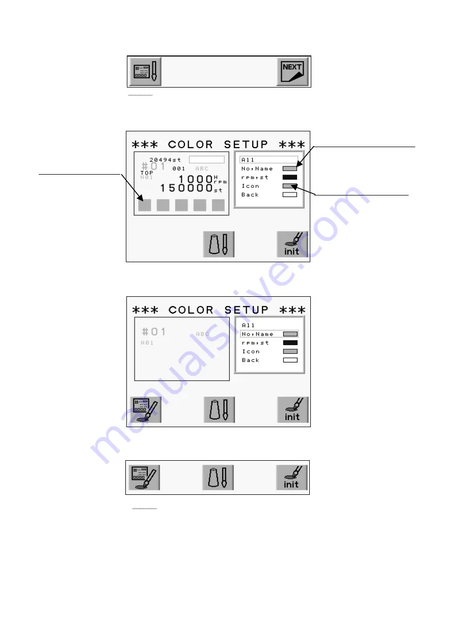
Press the A-Key.


(A-Key)   (B-Key)    (C-Key)    (D-Key)    (E-Key)


            6) The Color Set-Up Menu displays. 

Use the Jog Keys to select a color. 


(A-Key)   (B-Key)    (C-Key)   (D-Key)   (E-Key)


7) Choose the item.


(A-Key)   (B-Key)    (C-Key)   (D-Key)   (E-Key)


8) Press the A-Key.


(A-Key)   (B-Key)    (C-Key)   (D-Key)   (E-Key)


Color for the chosen item


The screen thumbnail 

Set Color for Each Item


                                                3-13 

Summary of Contents for BEVT Series

Page 1: ...Instruction Manual...

Page 2: ...3 6 6 Switching Screens 3 7 7 The Information on the Screen 3 8 8 The Information on the Extension Screen 3 9 9 Messages 3 11 10 Message to Start the Machine 3 11 11 Color Setting of the Display 3 12...

Page 3: ...umbnail 7 4 4 Production 7 5 5 Changing the Design Name 7 5 6 Color Change Function Code 7 6 7 Thread Consumption 7 7 8 Deletion of the Design 7 9 9 USB Direct Drive 7 10 Chapter 8 Programs 1 Changing...

Page 4: ...ign Scheduled Download 12 9 8 Scheduling 12 10 9 Information on the Designs Scheduled 12 11 10 Automat ID 12 12 11 LAN Board Set Up 12 13 12 Initializing the LAN Board 12 15 13 LAN Board Parameters 12...

Page 5: ...Chapter 1 Safety Instructions This chapter contains information on the following 1 Safety Instructions 2 Grounding Instrustions 3 Warning Labels 1 1...

Page 6: ...at know how to operate the machine should run the machine Do not let other personel operate the machine Operate the machine only from the front Do not load work to the machine from the back side Keep...

Page 7: ...or electrical shock Call for a service technician to fix the cable Keep water or chemical substances away from the controller Disconnect the power to the machine and call a service technician Keep me...

Page 8: ...e needle or damage the fabric Do not force the fabric while sewing It can cause the needle to break or bend Turn OFF all power switches and unplug the power cable after use Follow the lubrication inst...

Page 9: ...s GPay attention during operation to the parts labeled Warning Labels Contents Needle Hazard Warning Lable Hair Warning Label Take Up Lever Warning Label Frame Warning Label Hook Warning Label Belt Wa...

Page 10: ...Chapter 2 Introduction This chapter contains the following information 1 Specification 2 Advantage 2 1...

Page 11: ...nding 8 Main Motor 200V AC Servo Motor 9 Pantograph Drive Motor AC Servo Motor 10 Head Number 1 11 Speed 200 1200rpm Max Speed is defined for each model 12 Needle Number Max 15 Sliding Head 13 CF Card...

Page 12: ...e seen on the screen 6 Networking Optional Ethernet board allows the LAN networking of the machines Networked machines can share designs and monitored in real time 7 USB Port Optional USB board allows...

Page 13: ...y hold down the stop key till the pantograph reaches the desired position and then let go Press it again to stop the pantograph 16 Automatic speed control Jump The controller varies the speed of the m...

Page 14: ...Automat 2 Turning ON OFF the Machine 3 Origin Setting 4 Stand by and Drive State 5 Switching Menu Icon Keys 6 Switching Screens 7 The Information on the Screen 8 The Information on the Extension Scree...

Page 15: ...1 Automat 3 2...

Page 16: ...movement and the speed gradually increases Used to move the cursor for selecting 6 Page Key Switches screen Refer to Paging Screen 7 Menu Key Switches the Menu Icon Keys Refer to switching the Menu Ic...

Page 17: ...Origin Set When the machine is initially turned on the origin must be set 1 Refer to Turning ON OFF the machine turn ON the machine 2 The display shows the screen below after showing BARUDAN logo Pre...

Page 18: ...r to Drive in Start Sewing 1 Stand By mode Usually machine is in the stand by state when it is turned ON It is the state when sewing preparation takes place In this state the design data can be select...

Page 19: ...te If you selected one of the Menu Icon Keys and you want to quit it pressing The menu key exits the menu MENU1 MENU2 Sub MENU When Network is being set in the machine MENU1 5 2 Menu Icon Keys This ex...

Page 20: ...h it 9 Network Key Reads design data from the server 6 Switching the Screens Press the Page Key to change screens When NOT in Drive Mode Basic Screen Extension Screen 1 Basic Screen While IN Drive Mod...

Page 21: ...e Basic Screen Going back to the Stand By mode automatically switches the screen to the Basic Screen 7 Screen Information Basic Screen Information The screen shows design information for the currently...

Page 22: ...ng 9 Shows whether the data has High or Low speed Function 10 Shows the current stitch count when in the Drive mode 11 Total stitch count available in memory 12 Shows the number of stitches backtracke...

Page 23: ...tch count 7 Total number of color changes 8 The remaining number of stitches before the machine will stop to change bobbin The Bobbin Counter feature must be turned on 9 Thumbnail of the selected desi...

Page 24: ...Key or the Page Key to clear the message The A to D Key are not available while a message appears on the screen First clear the message before execute other functions 10 Message to Start the Machine T...

Page 25: ...the page The Jog Key chooses the color on the display Move Up Down the cursor with Up Down Key Move Left Right the cursor 11 2 Changing the Display Color 1 Press the Menu Key to display Menu 1 as belo...

Page 26: ...Set Up Menu displays Use the Jog Keys to select a color A Key B Key C Key D Key E Key 7 Choose the item A Key B Key C Key D Key E Key 8 Press the A Key A Key B Key C Key D Key E Key Color for the cho...

Page 27: ...C Key D Key E Key A Key to goes back to previous screen Press the E Key to save the change and go back to previous screen 10 Press the MENU Key to go out from the Color Set Up Menu 11 Press the A Key...

Page 28: ...A Key B Key C Key D Key E Key Press the B Key to Cancel the initialization 11 4 Items that can have colors changed Item Description Default Color Shows all the items in the thumb nail in set color Me...

Page 29: ...or each code displays Use the Jog Keys to select the needle color you want to change Chosen Needle Color A Key B Key C Key D Key E Key Press the C Key to go back to the display color setting screen C0...

Page 30: ...al color 3 primary colors New color 6 Change the value using the A B Keys The color pallet color changes depend on the entered value Original color New color A Key B Key C Key D Key E Key 7 Press the...

Page 31: ...screen 11 6 Changing Memory Design Color Color change List the color for each code Changes the color of the memory design bitmap and visual display 1 Refer to Changing the color in the display use th...

Page 32: ...C Key D Key E Key Press the A Key to change the color switching function icon Interchange The chosen one will be shown on the right Replace 6 Press the E Key A Key B Key C Key D Key E Key 7 Press the...

Page 33: ...and go to the Color Setup Screen 2 Press the C Key A Key B Key C Key D Key E Key 3 Color Setup Screen will appear Use the Jog Key and select B L or B R By pressing the origin key Tape and Cord will s...

Page 34: ...Key D Key E Key 2 Press the D Key to rewrite the Bitmap image on Memory Control Screen with the same colors as in the Color list A Key B Key C Key D Key E Key Press the C Key and then D Key together...

Page 35: ...he color list 1 Refer to Changing the color in the display and go to the Color Setup Menu 2 Press the C Key A Key B Key C Key D Key E Key 3 Press and hold the A Key until it beeps twice A Key B Key C...

Page 36: ...tions This chapter contains information on the machines manual operations 1 Color Needle Change 2 Trimmer 3 Thread Clamp 4 Appliqu 5 Frame Change 6 Bobbin Counter 7 Holding The Needle at the Dead Bott...

Page 37: ...Key E Key When the machine is first powered on the machine must be oriented to the correct Position After following the steps above the D14 message displays Press the The Start Key to orient the machi...

Page 38: ...above the D14 message displays Press the The Start Key to orient the machine 2 Thread Thrim 2 1 Thread trim operates the trimmer Manual trimming for both top and bottom thread 1 Press the Menu Key to...

Page 39: ...2 Bobbin Trimming Instructions for trimming the bobbin 1 Press the Menu Key to display Menu 1 as below 2 Press the C Key A Key B Key C Key D Key E Key 3 Press the A Key to trim the bobbin A Key B Key...

Page 40: ...ey to display Menu 1 as below 2 Press the D Key A Key B Key C Key D Key E Key 3 Press the B Key A Key B Key C Key D Key E Key 4 The Start Switch message appears Press the Start Key A Key B Key C Key D...

Page 41: ...Press the C Key to go back to previous screen 5 Press the C Key to go back to previous screen without moving the pantograph A Key B Key C Key D Key E Key 6 Bobbin Counte r Bobbin Counter stops the ma...

Page 42: ...he previous setting appears on the screen Previous Setting column A Key B Key C Key D Key E Key Press the A or B Key to increase decrease the count by 100 stroke Press and hold the C Key then press th...

Page 43: ...Press the D Key A Key B Key C Key D Key E Key 3 Press the C Key A Key B Key C Key D Key E Key 4 The machine requires a Start Switch Press the Start Key The machine stops as the needles penetrates the...

Page 44: ...ices It works while sequin device are at the bottom Ready to feed sequins 4 Press the Manual Key to go out from the Sequin Setting Menu 8 2 Head Adjustments 1 Refer to Sequin Setting Menu find the men...

Page 45: ...3 Press the D Key to go out from the adjustment A Key B Key C Key D Key E Key 4 Press the MENU Key to return to the Basic Screen 4 10...

Page 46: ...Chapter 5 Loading Designs This chapter explains how to load designs to the machines memory 1 Before Loading Designs 2 ABC Drive 3 Loading from PC 4 Saving to PC COM 5 Adding Stitches 5 1...

Page 47: ...eft hand corner of the screen 2 Choosing a design Same procedure as saving design The list of the designs on the FD or on the machines Memory displays during this operation Use the Jog Keys to select...

Page 48: ...cation must be available ABC Drive will not work when machine is in Drive mode Refer to Loading from PC for the connection 1 Prepare the device sending the design 2 Press the Menu Key to display Menu...

Page 49: ...ancel the ABC Drive Then press the A Key to delete the ABC Drive Design and exit ABC Drive A Key B Key C Key D Key E Key 1 A blank Memory location will automatically be chosen for ABC Drive If the occ...

Page 50: ...Menu Key to display Menu 2 as below 3 Press the A Key A Key B Key C Key D Key E Key 4 Press the A Key to toggle the Device icons Choose the COM icon Refer to Before Loading A Key B Key C Key D Key E K...

Page 51: ...mpty location if the Memory is full 2 The B Key toggles the Tape Code as U F EL Other codes are not valid 3 the data transmission speed is chosen from the chart below The D Key toggles the No assigned...

Page 52: ...ey C Key D Key E Key When an occupied Memory location is chosen the icon above the C Key will be 6 Press the C Key to merge the design A Key B Key C Key D Key E Key Press the C Key again to cancel the...

Page 53: ...e RS 232C serial port The cable should be Cross or Reverse null modem The machines with the LAN port cannot use the COM connection 1 Prepare the device receiving the design 2 Press the Menu Key to dis...

Page 54: ...mory is full 2 The B Key toggles the Tape Code as U F EL Other codes are not valid 3 the data transmission speed is chosen from the chart below The D Key toggles the No assigned to the speed No Speed...

Page 55: ...oose the Jog icon A Key B Key C Key D Key E Key The icon at the upper left hand corner of the screen should be 4 The designs in memory display Choose a Memory location to save the jog movement A Key B...

Page 56: ...ntil you hear a short beep to write a Jump Stitch to the memory 2 A Key B Key C Key D Key E Key 1 Choose a Jump or a Stitch to save to the memory 2 The scale rotation will effect the added stitches 5...

Page 57: ...the E Key to start the Copy 2 A Key B Key C Key D Key E Key Press the B Key to go to the Jog menu 1 The scale and rotation of the original design effects the copied design The Jog stitches and the co...

Page 58: ...ting Folders on the USB Memory 4 Saving to the USB Memory 5 Loading from the USB Memory 6 Memory Back Up 7 Loading the Back Up Design 8 Deleting Designs on the USB Memory 9 Deleting Folders on the USB...

Page 59: ...e image data for each design file The image can be viewed on PCs Back Up all design files stored on the machine b System software update The USB Memory updates the system software quickly USB Memories...

Page 60: ...emory needs to have folders to store files A USB Memory can have Folders up to 50 Max 50 Folders Max 100 Files Inactive Max 30 Files Max 100 Files USB Memory Design Files FDR Folder FDR Folder PRJ Fol...

Page 61: ...r Stores TFD format design files Created only on PC 5 Files not able to be handled The Automat cannot handle folders saved into another folder Add extension behind of the folder name when creating fol...

Page 62: ...ss the B Key A Key B Key C Key D Key E Key 3 Press the E Key A Key B Key C Key D Key E Key 4 Press the D Key A Key B Key C Key D Key E Key 5 The folders in the USB appear on the screen A Key B Key C K...

Page 63: ...view the enlarged thumbnail The design files in the FDR PRJ TFD folders are sorted in alphabetic order 3 Creating a Folder Instructions for creating folders folders on a USB Memory FDR PRJ MEM Folders...

Page 64: ...gin key A Key B Key C Key D Key E Key Use the Jog keys to select a letter Press the Origin Key or the B Key to enter the letter Press the A Key to delete the last letter Press the C Key to cancel crea...

Page 65: ...same name 1 Refer to the USB Memory Screen and find it 2 Press the A Key A Key B Key C Key D Key E Key 3 Use the Jog keys to select the destination folder A Key B Key C Key D Key E Key 4 Press the B...

Page 66: ...Each folder FDR PRJ MEM stores the design in a different format Refer to Before Using the USB Memory for the differences between each folder 5 Loading from the USB Memory Instructions for loading des...

Page 67: ...properties The Enter icon will not display and loading a design will not be possible 5 Press the E Key to start loading the design to the memory A Key B Key C Key D Key E Key 1 The controller automati...

Page 68: ...design to merge A Key B Key C Key D Key E Key Press the A Key for the previous screen Press the B Key to toggle the USB and Memory screen Press the C Key to view the design property The icon above the...

Page 69: ...tructions on how to back up the designs in the Memory Merging is not allowed This operation is not allowed in the Stand By State 1 Refer to Creating a Folder and create a MEM Folder The icon above the...

Page 70: ...p and go out from the menu 7 Loading Design Back Up Instructions on how to load the design back up into the machines memory 1 Refer to the USB Memory Menu and display it 2 Choose a MEM folder to load...

Page 71: ...g and exit 8 Deleting Designs on the USB Memory Instructions on how to delete files from a USB Memory 1 Refer to the USB Memory Menu and display it 2 Use the jog keys to select the design to delete 3...

Page 72: ...is deleted all designs in the folder will be deleted as well 1 Refer to USB Memory Menu and display it 2 Use the jog keys to select the folder to delete 3 Press the B Key A Key B Key C Key D Key E Key...

Page 73: ...Choose a checked design and press the Origin Key to retrieve it 3 Press the E Key to start saving the designs A Key B Key C Key D Key E Key 11 Loading Multiple Designs at the same Time 1 Refer to Load...

Page 74: ...3 Press the E Key to start loading designs A Key B Key C Key D Key E Key 6 17...

Page 75: ...tions 1 Switching Designs 2 Design Information 3 Design Thumbnail 4 Production 5 Renaming the Design 6 Color Change Function Code 7 Thread Consumption 8 Deleting the Design 9 USB Memory Direct Drive T...

Page 76: ...of designs in the memory and displays memory location design name and stitch count When a location is empty it is shown with A Key B Key C Key D Key E Key 4 Use the jog keys to select a design Press...

Page 77: ...design measured in tenths of millimeters P2 Distance between the start point and top right corner of the pattern measured in tenths of millimeters Free St Total number of stitches available in memory...

Page 78: ...y C Key D Key E Key 4 The Thumbnail appears Thumbnail of design with Program parameters changed A Key B Key C Key D Key E Key Press either A D Key to go back to the previous screen 5 Press the E Key t...

Page 79: ...ttern and totoal number of times all patterns in the memory combined have been sewn Press the D Key until a long beep is heard to reset the Stitch count and piece Count for the selected design Press t...

Page 80: ...creen 1 The design name can contain a maximum of 8 characters The first letter must be one an alpha character Saving the design to a floppy disk or USB Memory converts the alpha characters to capital...

Page 81: ...Display to change the color 4 Press the A of B Key to change the code The modified code will be highlighted A Key B Key C Key D Key E Key Press the D Key for the previous screen A design can have up...

Page 82: ...displays Use the jog keys to select a column A Key B Key C Key D Key E Key Press the A Key to decrease the value Press the B Key to increase the value Press the C Key to change the set Up method 1 Pr...

Page 83: ...tches Adjusting Value The calibration ratio of thread consumption 100 200 100 8 Deleting a Design Instructions on deleting a design from memory The machine must be out of Drive mode to delete designs...

Page 84: ...designs in memory by pressing the D Key while the C Key is held Press the A or E Key to cancel deleting and go back to the previous screen 9 USB Direct Drive 9 1 USB Direct Drive Designs saved on the...

Page 85: ...B Key C Key D Key E Key Press the B or C Key to choose the Memory location for the design 5 Press the A Key A Key B Key C Key D Key E Key 6 The design file is listed in the Folder Use the jog keys to...

Page 86: ...aded and the controller goes into Drive mode A Key B Key C Key D Key E Key 9 2 Searching a Design on the USB Memory 1 Refer to the USB Direct Drive and display the menu 2 Press the D Key A Key B Key C...

Page 87: ...to be searched 4 Press the E Key to start searching A Key B Key C Key D Key E Key 5 The search result displays Use the jog keys to select design to load A Key B Key C Key D Key E Key 6 Press the Driv...

Page 88: ...am Parameters This chapter includes instructions on applying program parameters to a design 1 Changing the Program Parmeters 2 Setting the Sub Soft Limits 3 Setting the Matrix Embroidery 4 Program Par...

Page 89: ...he machine is in Stand By state While in Drive mode the Program parameters can only be viewed 1 Refer to the Switching Designs and display the list The list will not display while in Drive mode 2 Pres...

Page 90: ...Condition Parameters MC 1 Refer to Changing the Program Parameters and display the list 2 Use the jog keys to the move the the cursor Frame type 3 Select the value 1 to 3 0 leaves the Sub Soft Limit i...

Page 91: ...C Key D Key E Key 3 Setting up a Matrix 3 1 Setting the Design Size The feature automatically repeats the design in the Embroidery Area The layout is calculated from the distance between the center o...

Page 92: ...8 Press the C Key to redraw the screen for the new setting A Key B Key C Key D Key E Key 9 Press the D Key to go back to the Program List A Key B Key C Key D Key E Key 10 Press the E Key to change the...

Page 93: ...the Origin Key to display the menu below 5 Press the E Key A Key B Key C Key D Key E Key Item Function Range Default The Pantograph movement to V X in m m Regarding the Soft Limit setting 100 The Pant...

Page 94: ...ress the C Key to redraw the screen for the new setting A Key B Key C Key D Key E Key 9 Press the E Key to go back to the Program List A Key B Key C Key D Key E Key 10 Press the D Key to change the fo...

Page 95: ...n mm H Soft Limit setting The size of the pattern to V X Direction in mm V 1000 to 1000 Space Space The size of the pattern to H Y Direction in mm H 1000 to 1000 Set the margin along the frame to V X...

Page 96: ...deg 6 90 deg 7 180 deg 8 270 deg 4 Angle Rotation in 1 degree increments 0 89 degree 0 deg 5 Origin Automatically returns the pantograph to the pattern origin when sewing is completed 1 Active 0 Inac...

Page 97: ...s the value set 9 A V Offset When A V Offset is 0 the Pantograph does not move to side 10 Frame The Pantograph offset at the end of the design 1 Active 0 Inactive 0mm 11 F H Offset When the Frame para...

Page 98: ...omatic layout 1 Active 0 17 V X Repeat Sets the repetition of the pattern in the Matrix layout Total of repetition 1 V H 400 18 H Y Repeat 19 V Space Width Direction Sets the gap between the pattern 0...

Page 99: ...cale the stitch length with the Swing parameter in the MC setting O V and H 1 V X Only 2 H Y Only 0 Matrix Sewing Order Example 3 patterns in width and 2 patterns in depth Start Dir 1 Start Dir 2 Star...

Page 100: ...ewing patterns in memory 1 Start Point 2 Drive Mode 3 Speed 4 Trace 5 Float 6 High Speed Float By Stitch Count 7 High Speed Float By Color Change Code 8 Color Change Code Teaching 9 Function Codes 10...

Page 101: ...e to the Start Point of the selected By pressing the Origin Key The Pantograph moves to the Absolute Origin machine origin 2 Drive Mode Instruction for putting the machine in Drive mode The machine ca...

Page 102: ...fore using this feature The Pantograph traces a rectangle to see if the machine is sewing at the right position and right size This feature is only available in Drive mode BEFORE sewing begins The rec...

Page 103: ...order 4 2 Outline Trace Be sure the Frame Limit parameters in the MC Machine Condition are correctly set before using this feature The Pantograph traces the outline of the design to see if the machine...

Page 104: ...ay MENU 2 as below 2 Press the D Key A Key B Key C Key D Key E Key 3 The Float Screen appears Press the Start Switch for the Float A Key B Key C Key D Key E Key Exiting Float a Press to stop the machi...

Page 105: ...ey B Key C Key D Key E Key 3 Press the E Key to move the Pantograph to the position where the stitch count is appointed A Key B Key C Key D Key E Key Exiting Float a Press to stop the machine b Press...

Page 106: ...moves to the selected color change location A Key B Key C Key D Key E Key Exiting Float a Press to stop the machine b Press the Menu Key to display MENU 2 c Press the D Key A Key B Key C Key D Key E...

Page 107: ...e the Color Code Press the C Key to convert it into the Stop Code A Key B Key C Key D Key E Key 6 Press the Start Switch to resume sewing with the new code The figure below shows how the Color Code ch...

Page 108: ...ow 2 Press and hold the C Key until the machine beeps twice A Key B Key C Key D Key E Key 3 The Function Code Screen appears Press the A or B Key to change the Function Code A Key B Key C Key D Key E...

Page 109: ...lit The Start Switch starts the sewing at the point were the machine back up to 1 Stop the machine with the Stop Key 2 Press and hold the Automending Switch at the Tension Box on the sewing head whic...

Page 110: ...n it left off at 1 Turn ON the power of the machine 2 Press the E Key to find the machines origin A Key B Key C Key D Key E Key 4 The Stand By Screen displays Press the D Key to continue sewing Press...

Page 111: ...apter 10 Teaching This chapter contains the instruction for changing Function codes This method of T Each is quicker than chaning codes while the design is sewing 1 Color Codes 2 All Function Codes 10...

Page 112: ...ey A Key B Key C Key D Key E Key 3 The Color Code Screen displays Press the E Key to search the next Color Change Code A Key B Key C Key D Key E Key The screen automatically closes if no Color Change...

Page 113: ...y C Key D Key E Key 3 The Function Code Screen displays Press the E Key to search the next Code A Key B Key C Key D Key E Key The screen automatically closes if a function code is not found It searche...

Page 114: ...5 Press the E Key to save the change and search the next Function Code The figure below shows how the Function Code was changed C00 A Key B Key C Key D Key E Key 10 4...

Page 115: ...Machine Condition This chapter contains information on the machine s machine conditions 1 Changing the Machine Conditions MC 2 Resetting the Machine Conditions MC 3 Description of Machine Condition pa...

Page 116: ...ow 2 Press the D Key A Key B Key C Key D Key E Key 3 Press the E Key A Key B Key C Key D Key E Key 4 Press the A Key A Key B Key C Key D Key E Key 5 The MC List appears Use the jog keys to select a pa...

Page 117: ...ed at this time They are saved when MC is exited The new values would not be valid if the power is cut before saving 7 Press the Manu Key when all the settings are done 8 Press the A Key to save the n...

Page 118: ...is operation is only available in the Drive state 1 Refer to the MC Change to find the MC List 2 Press and hold the E Key for 2 short beeps A Key B Key C Key D Key E Key 3 Press the A Key to initializ...

Page 119: ...ues above to create a stitch and converts it into a lock stitches 1 4 11 14 1 The thread clamp control when start sewing after a trimming 4 Clamp Type 1 Opens for 1st stitch Close at the DBC Opens for...

Page 120: ...evolution A stitch longer than the programmed value is divided into two stitches 30 127 127 11 Controls the number of stitches the machine will automatically back up at a thread break Stitch Back 0 7...

Page 121: ...d Origin return Trace allowed The Jog Key operation is always allowed 0 2 0 17 Determines if the needle is lowered after a thread break for easier threading Needle Down 1 Active 0 Inactive 0 1 1 18 Ap...

Page 122: ...e panto can move to the right of the mechanical origin Right Limit 0 3200mm 115mm 23 Sets the left soft limit allowable distance panto can move to the front of the mechanical origin Left Limit 0 3200m...

Page 123: ...Elite Pro II 200 1300 rpm 800 Set a load factor of main shaft for the warm up function 32 Warm up end When the set value is set 100 the warm up function doesn t work This function works for the Elite...

Page 124: ...0 Max Needle No 0 39 Enter the number of the needle that has the borer 0 No borer used 0 Max Needle No 0 40 0 50 0 Value for sequin SQ L2 Not available R2 Not available TSQ L2 Left side on Right devic...

Page 125: ...Ethernet Port 1 Before Using the Network System 2 Registration of the Operator Code 3 Break Call 4 Operator Call 5 Time Out 6 Downloading Design Direct Download 7 Downloading Design Scheduled Downloa...

Page 126: ...is The Network System automatically recovers the connections between the Server and the embroidery machines 2 Operations The Network has 2 major functions Logging the machine status Uploading Download...

Page 127: ...ap image of the design 2 Hold the E Key if the transmission does not stop The controller cancels the transmission only when it is stopped 3 The LAN cable may vary up to the connection schematic Refer...

Page 128: ...isplay MENU 2 as below 2 Press the E Key A Key B Key C Key D Key E Key 3 Press the A Key A Key B Key C Key D Key E Key 4 The Operator Code List displays Use the jog keys to select the operator code A...

Page 129: ...s the C Key A Key B Key C Key D Key E Key 4 The Registration Screen displays A Key B Key C Key D Key E Key Use the jog keys to select a letter Press the Origin Key or the B Key to enter the letter 1 P...

Page 130: ...Press the B Key to delete the Code A Key B Key C Key D Key E Key 3 Press the D Key to confirm and delete A Key B Key C Key D Key E Key Press the B or E Key to cancel return to the previous screen 3 B...

Page 131: ...ess the Menu Key to display MENU 2 2 Press the E Key A Key B Key C Key D Key E Key 3 Press the C Key to call the Server A Key B Key C Key D Key E Key 5 Time Out Instructions to report that the machine...

Page 132: ...instruction manual for operation instructions 1 Press the Menu Key to display MENU 2 as below 2 Press the E Key A Key B Key C Key D Key E Key 3 Press the E Key A Key B Key C Key D Key E Key 4 Press th...

Page 133: ...Press the C Key to move to a lower numbered Memory location Press the D Key to move to a higher numbered Memory location 8 Press the E Key to start downloading A Key B Key C Key D Key E Key 7 Download...

Page 134: ...to view the information about the design to be downloaded 6 Press the E Key to start downloading A Key B Key C Key D Key E Key 8 Appointed Designs The Server can apooint designs to machine s The mach...

Page 135: ...ey D Key E Key Press the B Key to return to the previous screen 9 Information about Appointed Designs The instruction for viewing design information for the appointed designs 1 Refer to Appointed Desi...

Page 136: ...for registering the Automat ID 1 Disconnect the LAN cable from the machine and turn ON the machine 2 Press the Menu Key to display MENU 2 as below 3 Press the E Key A Key B Key C Key D Key E Key 4 Th...

Page 137: ...tions for setting up the LAN board 1 Refer to Automat ID and find the Registration Screen 2 Press the C Key to find the Set Up Screen A Key B Key C Key D Key E Key 3 Use the jog keys to scroll through...

Page 138: ...ering is available only for IP Address Subnet Mask and Host Address A Key B Key C Key D Key E Key 6 Press the C Key to return to the previous screen A Key B Key C Key D Key E Key 7 Press the Menu Key...

Page 139: ...rt initializing A Key B Key C Key D Key E Key Press B Key to abort it 13 The List of the LAN Board Parameters No Item Description Default 0 0 0 0 1 IP Address The IP Address of the Automat 255 255 255...

Page 140: ...apter 13 System This chapter contains the instructions for updating the machines system software 1 System Software Update with the USB Memory 2 Initialization of the Memory 3 Date and Time Setting 13...

Page 141: ...og keys to select System Software from the list 6 Press and hold the E Key to start updating the System Software 7 The controller beeps a long beep then restarts if the System Software Update was prop...

Page 142: ...ne 3 Release the A Key after the controller beeps Date Time Setting Screen appears A Key B Key C Key D Key E Key 4 Press the A or B Key to choose the value to change A Key B Key C Key D Key E Key 5 Pr...

Page 143: ...Chapter 14 Appendix This chapter contains the following lists as a reference 1 Function Codes 2 Error Messages 14 1...

Page 144: ...H High Speed HJ High Speed Jump T1 Top Thread Trimming T2 Bobbin Trimming The following Codes are called as The Color Change Codes G1 Group 1 G2 Group 2 SE Sub End C00 Stop C01 Needle Bar 1 Depends on...

Page 145: ...nk stroke of the Pantograph for the Socks feature There is no Function Code following Calculating Please wait Memory Full Delete designs Too many color changes The 401st and following Color Change Cod...

Page 146: ...Trip Try to restart the machine Turn OFF the power and check the bind by turning the Main Shaft with hands Main Motor Overload Turn OFF the machine and check the bind by turning the Main Shaft with h...

Page 147: ...e pattern to be fixed No further Stitch Back Automending due to the Color Change Code Trim the thread for further Stitch Back Automending Servo Driver Error Call technician Wrong Dip Switch Setting on...

Page 148: ...Embroidery Machine BEVT series Mechanical Guide...

Page 149: ...5 Threading the Sewing Head 1 7 Sewing Head Controls 1 10 Thread Break Detection 1 10 Replacing Bobbins 1 10 Stitch Theory 1 11 Needle Anatomy 1 12 Tension Adjustments 1 13 Adjusting The Top Tension 1...

Page 150: ...ine 2 1 Machine Lubrication 2 1 Bobbin Case Maintenance 2 8 Hook Assembly Maintenance 2 8 Chapter 3 Troubleshooting 3 1 Quick Fixes 3 1 Take Up Spring Replacement 3 4 Hook Timing 3 5 Position Finger A...

Page 151: ...Preparation The machine must be located near a grounded electrical outlet At least 6 of clearance are necessary between the back of the machine and any walls Also 36 of room are needed in front of th...

Page 152: ...he crate when it was received i e a photograph of the packaging may be necessary External damage is covered by the freight carrier so it is important to distinguish between internal and external damag...

Page 153: ...es is the equipment grounding conductor If repair or replacement of the cord or plug is necessary do not connect the equipment grounding conductor to a live terminal Check with a qualified electrician...

Page 154: ...e is doubt as to whether an outlet box is properly grounded consult a qualified electrician BEVT Series Mechanical Guide Machine Basics 1 4 Illustration above may not match the type of connectors in y...

Page 155: ...achine to detect thread breaks 6 Thread Break Switch Enables disables thread break detection on each head 7 Automend Button Controls the reversing of the pantograph for repair work or overstitching 8...

Page 156: ...BEVT Series Mechanical Guide Machine Basics 1 6 Z9 Sewing Head...

Page 157: ...the thread that is threaded through the tension unit with a square knot and gently pull it through the sewing head Repeat for each needle To completely rethread a sewing head follow these steps which...

Page 158: ...tween the silve wheels and over the take up spring NOTE To ensure proper threading pull the thread down and check that the take up spring bounces up and down with the thread movement 7 Thread through...

Page 159: ...1 9 Machine Basics BEVT Series Mechanical Guide...

Page 160: ...the switch is in the up position and off in the down position Thread Break Detection The Thread Break detection is sensed by the white nylon disks When the wheel for the needle sewing does not spin t...

Page 161: ...from the bobbin case Replacing the Bobbin Case 1 Hold the latch on the bobbin case open positioning the case on the shaft of the hook assembly ensuring that the bobbin remains in place 2 Make sure the...

Page 162: ...e needle starts downward and penetrates the fabric 2 The needle reaches its lowest point then begins to rise forming a loop of thread behind the needle 3 As the needle rises the hook point passes behi...

Page 163: ...the embroidery Factors such as the type of material you are using the tightness of the fabric in the hoop the backing used the size and style of lettering and the type of thread being used will all p...

Page 164: ...g thread type and letter size Bobbin Tension Problem The middle row of I s in the illustration above show almost no bobbin thread All the letters have the same problem so the bobbin tension needs adju...

Page 165: ...f the thread does not flow freely loosen the pressure on the spring that holds the disk down by turning the thumb nut counterclockwise 2 If the thread flows too freely increase the pressure on the spr...

Page 166: ...obbin case To test the tension insert a bobbin in the case and slowly pull the end of the thread The thread should unwind slowly and smoothly out of the bobbin case yielding a slight resistance Experi...

Page 167: ...breaks The machine keeps stopping but the thread is not broken When this occurs the tension take up spring is too tight Adjusting the Take Up Spring 1 To loosen the tension insert a screwdriver into...

Page 168: ...f the sheet PILLOW CASES The monogram should be centered between the edge of the open end and the stitching on the hem or the border pattern SHIRT POCKETS 1 4 to 1 2 down from the pocket edge and cent...

Page 169: ...idelines A loose knit fabric can be embroidered but without selecting proper stitch density and backing the garment can be stretched and possibly cut The operator s concern is to keep fabrics from str...

Page 170: ...generally more expensive but are more popular with experienced operators No Show Transparent backing used for light colored knit and stretch fabrics Water Soluble Topping Water soluble plastic is use...

Page 171: ...e Insertion When the machine is received all needles should be in place However from time to time it may be necessary to change a needle Replacing a Needle 1 Turn off the main power to the machine 2 M...

Page 172: ...commended for highly detailed patterns or pique knits Golf Shirt 100 Cot ton 70 10 to 80 12BP 2C or 3T Optional Topping recommended for highly detailed patterns or pique knits Leather 70 10 to 80 12WP...

Page 173: ...ng Plastic wrap is preferred on bulky knits because it pre vents the wales from poking up through the stitching after repeated washings Sweatshirt 70 10 to 80 12BP 1 or 2C Optional Highly detailed pat...

Page 174: ...oil that may splatter when the machine is oiled A maintenance log attached to the machine is recommended Keep a chart of the daily weekly etc maintenance performed on the machine Machine Lubrication...

Page 175: ...2 2 Machine Care BEVT Series Mechanical Guide B2 A1 B2 F1 B3 B3 C4 C4 C4 C4 E3 E3 E3 E3 C3 C3 C3 C3 E2 E2 C4 C4 C1 C1 C2 C2 B1 B1 E1 E1 C5 C5 E1 E1 E4 E4 EBEVT Z901CA Oiling Diagram...

Page 176: ...machine oil Clear mineral oil for sewing machinery Wipe lightly with cotton swab saturated in oil Once a month Needle Bar Crank Rod C1 Bearing oil Once a week Take Up Drive Lever C2 Needle Bar Drive L...

Page 177: ...2 4 Machine Care BEVT Series Mechanical Guide A1 B2 B2 B2 F1 B3 C4 C4 E3 E3 C3 C3 E2 C4 C1 C2 B1 E1 C5 E1 E BEVT Z1501CB Oiling Diagram...

Page 178: ...machine oil Clear mineral oil for sewing machinery Wipe lightly with cotton swab saturated in oil Once a month Needle Bar Crank Rod C1 Bearing oil Once a week Take Up Drive Lever C2 Needle Bar Drive L...

Page 179: ...2 6 Machine Care BEVT Series Mechanial Guide B3 C4 C4 E3 E3 C3 C3 E2 C4 C1 C2 B1 E1 C5 E1 E4 E4 E4 E4 C1 F1 B2 B2 B2 A1 C2 C5 BEVT Z1501C Oiling Diagram...

Page 180: ...oil for sewing machinery Wipe lightly with cotton swab saturated in oil Once a month Needle Bar Crank Rod C1 Bearing oil Once a week Take Up Drive Lever C2 Needle Bar Drive Lever 2 C3 Needle Bar Drive...

Page 181: ...e cleaned every 4 to 6 hours when the machine is used in a normal production setting The hook assembly should be oiled every 4 to 6 hours Cleaning the Hook Assembly 1 Remove the bobbin case from the h...

Page 182: ...mproper use of backing Backing should be hooped along with the garment If more stability is needed backing or topping should be bonded to the garment Improper tension Adjust the tensions so that only...

Page 183: ...d pulled out of bobbin case There should be at least three 3 inches of thread hanging from the bobbin case when it is replaced Needle inserted improperly Make sure the needle is inserted all the way i...

Page 184: ...tecting thread breaks Check if contacts are dirty Or the machine may be set for a boring device in MC Parameter 1 Check to make sure that the Borer parameter is at Thread Break Is Frayed Burr on eye o...

Page 185: ...ke up spring in reference to the assembly port There is a groove in back where the spring locks in place 6 Remove the worn take up spring 7 Insert the new spring placing it in the same position as the...

Page 186: ...of line The most common indication that the hook timing needs adjustment is when the machine fails to form and complete a stitch Checking the Hook Timing 1 Leave the needle and bobbin threaded and rem...

Page 187: ...reate an H O X test as follows Using a block alphabet program H O X in capital letters 20mm high into the machine These letters are used because they encompass all the various directions of the pantog...

Page 188: ...p the needle with this hole then adjust the position finger It is very critical that there is a gap between the nose and hook assembly This gap should be approximately 5 75mm to allow the bobbin and t...

Page 189: ...th and Hook Timing with optional Gauge The following instructions require Optional Needle Depth Gauge Part HB220040 Hook timing and needle depth can be checked at the same time using the Needle Depth...

Page 190: ...the gauge gently with an upward motion if necessary The tip of the needle should barely rub on the top of the gauge if the depth is adjusted properly Check the following Make sure main pulley is set...

Page 191: ...the proper depth is set Proper Needle Depth the eye of the needle should be visible in the hook basket when the main pulley is set to 0 degrees When using the Optional Needle Depth Gauge the tip of t...

Page 192: ...lowing instructions explain the removal of the Needle Bar Driver for replacement or inspections 1 Remove the middle thread guide and the front cover of the sewing head to gain access to the Needle Bar...

Page 193: ...ver Pin should be rotated so the bottom set screw aligns with the flat spot on the Needle Bar Driver Pin The Pin should be pushed against the bottom of the Needle Bar Driver so there is no play howeve...

Reviews: