WAM Arm – User’s Manual
www.barrett.com
© 2008 Barrett Technology®, Inc.
Document: D1001, Version: AH.00
7 of 80
3.
The WAM Cable Maintenance Guide covers the cabling of joints 1 through 4 and the general
rules for handling cables, and should be used in the event that a cable in the 4-DOF WAM is
damaged or is coming loose.
4.
The Wrist Cable Maintenance Guide covers the cabling of joints 5 and 6 and should be used
with the introductory sections in the WAM Cable Maintenance Guide in the event that a cable
in the Wrist is damaged
5.
The Inertial Specifications Manual presents the inertial data for the WAM robotic arm (the 4-
DOF version and both 7-DOF versions) in support of computed-torque control techniques.
6.
The Support Reference Sheet lists the variety of support options Barrett provides and assists
the customer in using the resource most likely to answer their question most effectively.
1.1.3 WAM
Arm
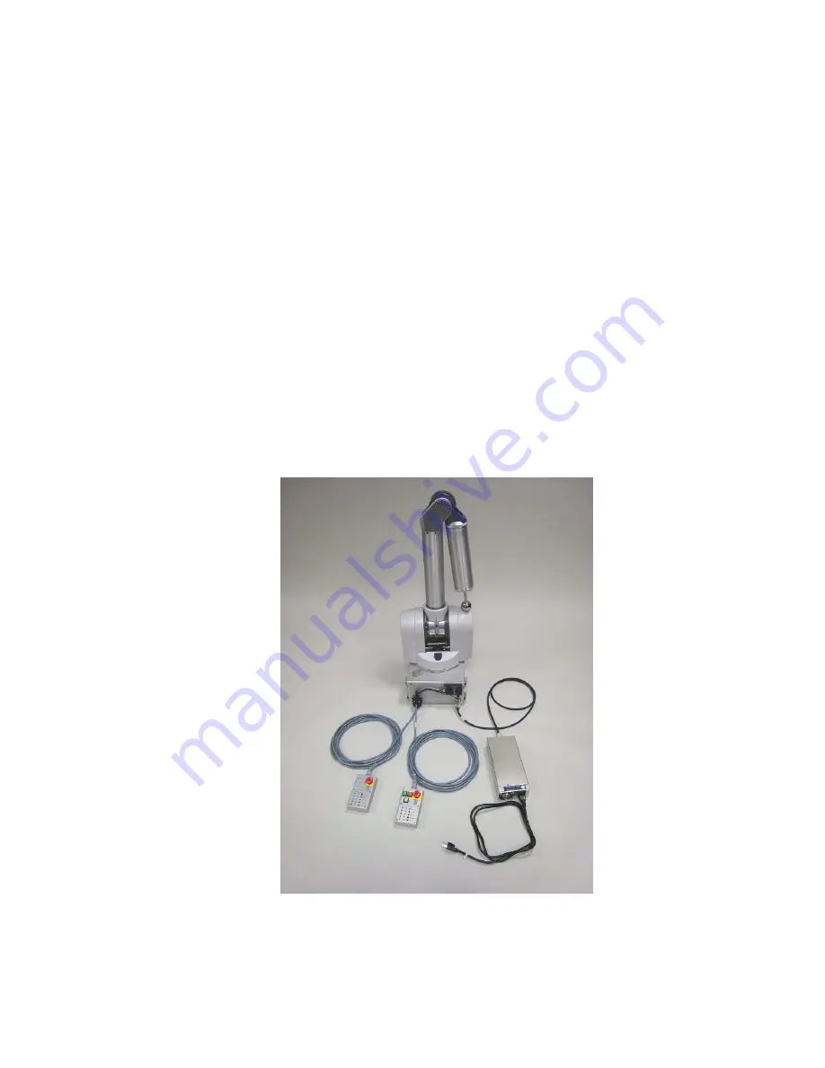
The standard four-degree-of-freedom WAM Arm, shown in Figure 1, has four cable-driven joints
labeled J1 through J4, and four brushless DC motors labeled M1 through M4. M1 controls the yaw
(J1) of the WAM and is located in the base of the WAM. Using Barrett’s patented cable
differential, M2 and M3 together control the pitch (J2) and roll (J3) of the WAM, and are
contained in the shoulder of the WAM. M4 controls the bend of the “elbow” (J4), and is located
just above M2 in the shoulder. Using Barrett’s Puck technology, all motor encoders, power
amplifiers, and controllers are located in a single compact package adjacent to each motor,
eliminating the need for a controller cabinet and heavy electrical cables.
Figure 1 - WAM Arm
The standard WAM Arm comes with an internal computer and a blank outer link (shown attached
to the end of the elbow in Figure 1 and shown in full in Figure 2). However, several options (see


