WAM Arm – User’s Manual
www.barrett.com
© 2008 Barrett Technology®, Inc.
Document: D1001, Version: AH.00
19 of 80
Error occurs in state
E-STOP
IDLE
ACTIVE
Velocity exceeds VL1
No action
Warn
Warn
Velocity exceeds VL2
No action
Fault, E-STOP
Fault, IDLE, Wait 1/4s
Torque exceeds TL1
Warn for non-zero
Warn for non-zero
Warn
Torque exceeds TL2
Fault
Fault
Fault, IDLE
Heartbeat missing
Warn
Warn
Fault, E-STOP
Voltage lower than VOLTL1
No action
Warn
Warn
Voltage lower than VOLTL2
Fault
Fault
Fault, IDLE
Voltage higher than VOLTH1
No action
Warn, Bleed voltage
Warn, Bleed voltage
Voltage higher than VOLTH2
No action
Fault, E-STOP
Fault, E-STOP
E-Stop pressed
Fault, E-STOP
Fault, E-STOP
Fault, E-STOP
NOTE: Warnings are cleared automatically, critical faults are cleared through a RESET
Request occurs in state
E-STOP
IDLE
ACTIVE
E-STOP
E-STOP
E-STOP
E-STOP
RESET / IDLE
Clear faults, power up
bus, enumerate, IDLE
Clear faults
IDLE
ACTIVATE
No Action
If no warnings or faults,
ACTIVE
No Action
REQUEST
ERROR
Figure 17 – WAM Responses to Errors and Requests
3 System
Setup
3.1 Mounting
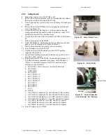
The mounting-surface for the WAM should be designed to handle the large reaction forces
generated at the base of the arm during high-acceleration operation. The WAM can be fastened to
a prepared mounting-surface in several ways. If you use four M10 or 3/8” screws, remove the
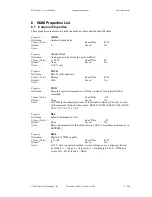
base cover to access the four bolt holes in the base plate. The holes are located on the base of the
WAM according to Figure 18 and Figure 19. The plate thickness is 8mm. If you use M12 screws,
you can screw upwards from the opposite direction, eliminating the need to removing the base
cover. Alternatively, the WAM can be mounted using the clamps provided in the maintenance kit.
It is important that the mounting surface NOT be grounded to earth ground (see “Grounding”
section below).
Figure 18 – Screw-hole Locations
Figure 19 – Mounting-Hole Measurements


