WAM Arm – User’s Manual
www.barrett.com
© 2008 Barrett Technology®, Inc.
Document: D1001, Version: AH.00
11 of 80
1.1.7 Electrical
Cables
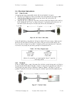
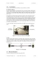
All necessary electrical cables are included with the basic WAM System, shown in Figure 9. An
AC Line Cord connects the Power Supply to a wall source. A blue DC Power Cable connects the
Power Supply or another DC power source to the WAM. If you purchased an external WAM PC,
a purple CANbus cable is provided for CAN communication with the WAM. The pendant cables
(shown attached to the pendants in Figure 8) connect directly to the WAM. An Ethernet cable is
also provided for the option of Ethernet communication with the WAM.
Figure 9 – Electrical Cables
1.1.8
Control Software and Firmware
The WAM’s internal computer has firmware and software that are preloaded before it is shipped.
Included with a copy of the source code in electronic form are:
1.
User’s Manual (this manual)
2.
Quick Start Guide
3.
Cable Maintenance Guide
4.
Inertial Specifications Manual
5.
Support Resources Reference Sheet
For more information about software and firmware, please see Section 4.
1.1.9 Maintenance
Kit
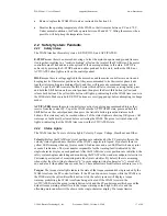
Included in each WAM package is a maintenance kit (shown in Figure 10). Use the maintenance
kit in accordance with the instructions in Section 3 and the Cable Maintenance Guide. The
maintenance kit includes the following:
•
1 Tool Plate (normally shipped attached to the Outer Link (or Wrist if purchased))
•
4 M10 Screws, Washers, and Nuts to secure the base
•
1 Set of Metric Hex Wrenches
•
1 Packet of Loctite 222
•
1 10-mm Combination Wrench
AC Line Cord DC Power Cable
CANbus Cable
Ethernet Cable


