R5911443 /02
UDM
94
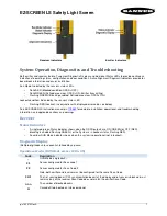
Image 8-50: Blend & Mask menu
2.
To enable blending, put the
Enable
switch to the right. The color of the switch becomes blue when enabled.
3.
To project masking lines on the screen, put the
Show lines
switch to the right. The color of the switch
becomes blue when enabled.
4.
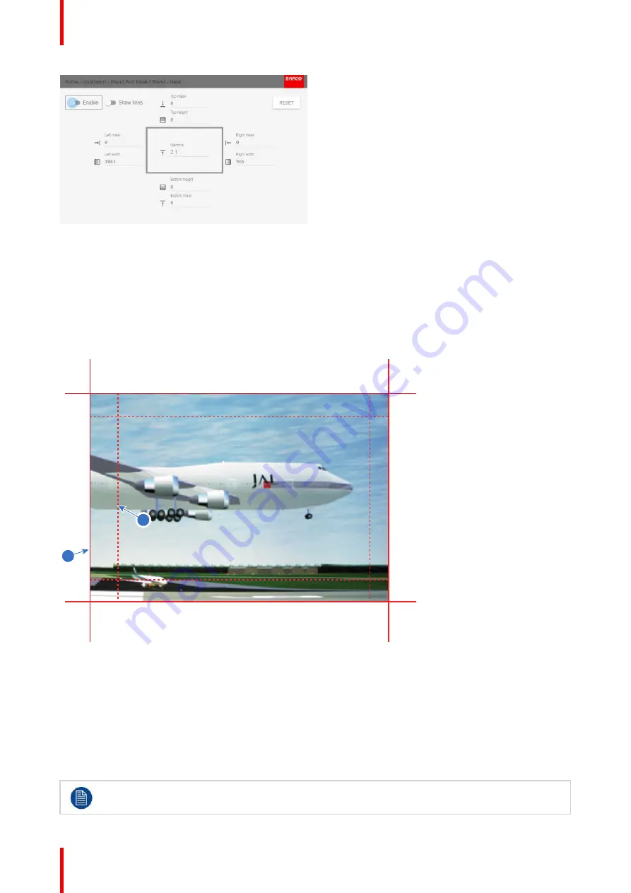
Determine the start position of the mask (1) for the masking height and width, together with the desired size of
the mask (2) to determine the width of the masked area.
When the blending lines are activated, you will get a visual indication of the screen of the installed blending
area.
1
2
Image 8-51
1
Start position (mask)
2
Blending width
5.
Select one of the four starting positions values with the arrow keys and confirm.
6.
Use the arrow keys or remote digits to change the value of the mask and confirm.
7.
Repeat this process for the desired width/height value.
8.
Repeat this process for all other desired sides.
Do not forget to disable the
Show lines
button after you achieved the desired blend zone.
Summary of Contents for UDM Series
Page 1: ...ENABLING BRIGHT OUTCOMES User manual UDM...
Page 22: ...R5911443 02 UDM 22 Safety information...
Page 48: ...R5911443 02 UDM 48 Input Communication...
Page 53: ...R5911443 02 UDM 53 4 To turn the test pattern off return to the previous menu GUI Introduction...
Page 54: ...R5911443 02 UDM 54 GUI Introduction...
Page 60: ...R5911443 02 UDM 60 GUI Source...
Page 112: ...R5911443 02 UDM 112 GUI Profiles...
Page 156: ...R5911443 02 UDM 156 Specifications...
Page 166: ...R5911443 02 UDM 166 Video timing tables...
Page 172: ...R5911443 02 UDM 172 DMX chart...
Page 176: ...R5911443 02 UDM 176 WiFi GSM compliance information...
Page 182: ...R5911443 02 UDM 182 Environmental information...