Barco – ISIS LFC – Installation Guide _____________________________________________________________ 21
Start starts the calibration. And once the calibration is started, it can be used to abort
the calibration.
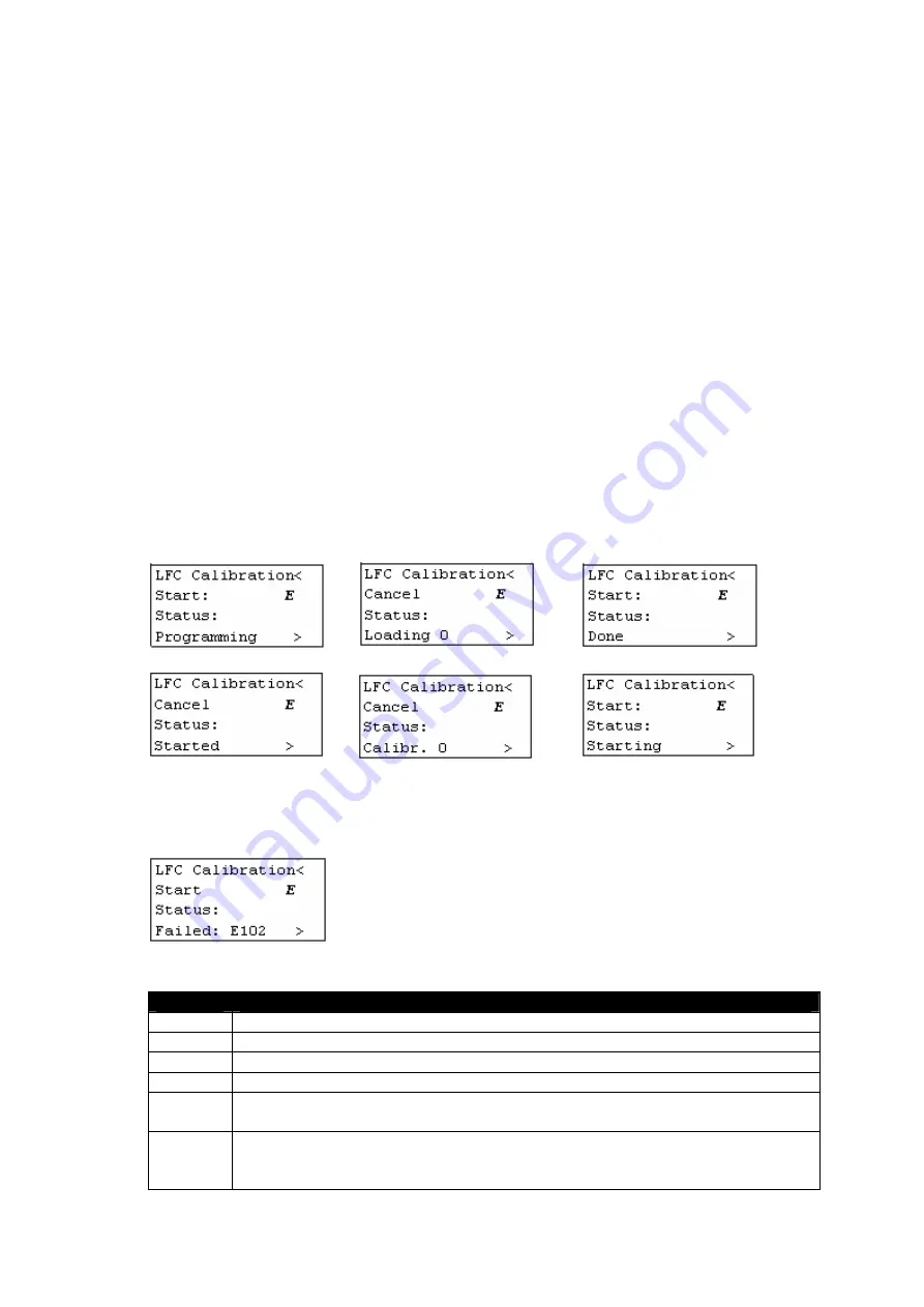
Status indicates status/progress of the calibration.
Press ENTER on Start: to start the calibration.
The different calibration steps:
1.
LFC calibration firmware is loaded into the LFC hardware.
The ‘Internal 2’ calibration table is copied to the ‘Internal 1’ calibration table. When
the calibration is done ‘Internal 2’ will be overwritten with the new calibration data.
2.
The LFC calibration software starts up and starts calibrating.
The Start: changes in a Cancel. Pressing ENTER on it cancels the calibration.
The progress is indicated on the keypad. Calibr. slowly increments from 0 up to 100.
This is the longest step and takes approximately 8 minutes. The calibration itself can
be followed on the OSD. (see further “OSD during calibration)
3.
When the calibration is done, the calibration data is transferred (loaded) to the display
main software.
4.
The display main software programs the calibration data into non-volatile memory
(into the ‘Internal 2’ table).
5.
The LFC hardware is loaded with the LFC compensation firmware.
The just calibrated table (‘Internal 2’) is loaded and LFC is enabled.
Faults:
If something goes wrong during calibration, the calibration is stopped and a fault code
is displayed:
The following error codes may appear:
Code
Description
E4
Occurs during step 1 when the calibration firmware could not be loaded.
E5
Indicates a hardware problem.
E6
Indicates a hardware problem.
E7
Indicates a hardware problem.
E101
Could not load calibration software from flash. Flash on LFC hardware
contains invalid or no LFC calibration software.
E102
Failure occurs during step 2, the test measurement fails. This could
happen when the optical sensor is not placed on the front of the display
or is not connected to the back.


