65
601–426 /15
F70 Series
In addition, four mounting inserts are located on the bottom of projector. See
Where possible, the projector lens must be positioned exactly perpendicular to the center of the
screen. Use the projector offset (lens shift), rather than physical angling, to correct any off-center
positioning.
CAUTION:
The position and physical securing of the projector must be sufficient to prevent it from
accidental or involuntary movement. Proper securing of the projector is the responsibility of the
installer and user.
CAUTION:
Always use a Rigging Frame when the projector shall be mounted in other ways than on
the feet, on a flat surface.
The threaded hole in the lower back end of the projector is NOT suitable for lifting or other heavy
operations. Only for adjustment purposes.
Installation and use of the Rigging Frame are described in document R5906768 Multifunctional
Frame — Installation Manual.
WARNING:
Maximum tensile load for each of the anchor points is 62,5 kg. This must be a major
consideration when designing the brackets or other arrangements for fixation of the projector.
WARNING:
A minimum of 4 anchor points must be used to secure the projector properly. It is
strongly recommended to use fixation points with as long mutually spacing as possible, on order to
increase mechanical stability of the installation.
Mounting on a flat surface
1.
Position the projector at the desired location.
2.
Power up the projector.
3.
Go to
Main Menu / Test Pattern
s and select an internal hatch pattern to display on the screen.
4.
Adjust the projector legs until the projected hatch pattern is a level and perfect rectangle.
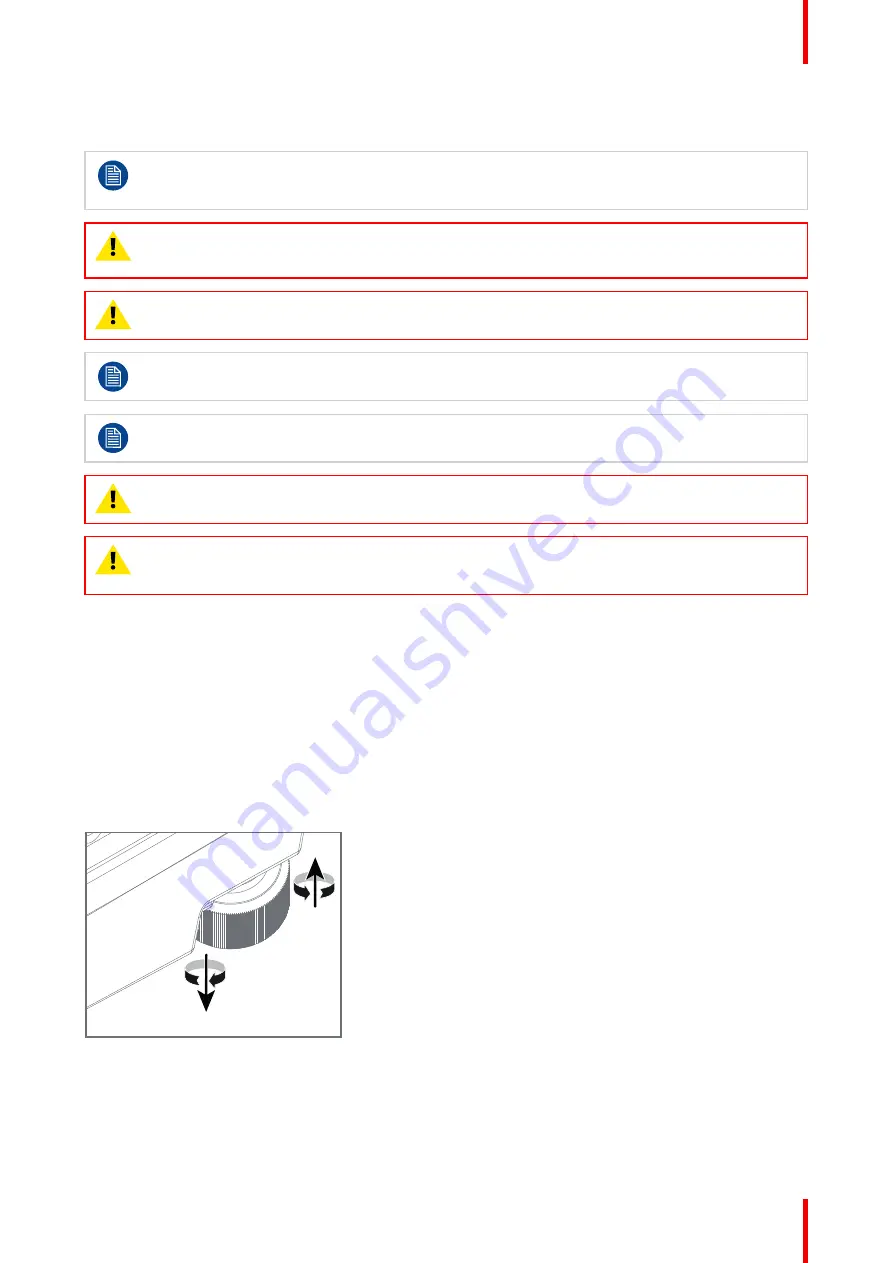
Adjustable feet
Twisting the adjustable feet in either direction, left or right, allows you to fine-adjust the projector position for
precise vertical mechanical alignment.
Raise
Lower
Image 4–2
Mounting to a ceiling
1.
Install the projector in to an approved rigging frame.
2.
Install the rigging frame to the desired location.
Summary of Contents for F70 Series
Page 1: ...ENABLING BRIGHT OUTCOMES User Manual F70 Series...
Page 10: ...601 426 15 F70 Series 10...
Page 60: ...601 426 15 F70 Series 60 Lenses Handling and features...
Page 82: ...601 426 15 F70 Series 82 Getting started...
Page 88: ...601 426 15 F70 Series 88 Source menu...
Page 162: ...601 426 15 F70 Series 162 System settings menu...
Page 166: ...601 426 15 F70 Series 166 GUI Status menu...
Page 170: ...601 426 15 F70 Series 170 3D...
Page 171: ...171 601 426 15 F70 Series 13 1 Upgrade procedure 172 Upgrade projector firmware 13...
Page 182: ...601 426 15 F70 Series 182 Technical Specifications...
Page 191: ...191 601 426 15 F70 Series C 1 DMX chart Basic 192 C 2 DMX chart Extended 193 DMX Chart C...
Page 216: ...601 426 15 F70 Series 216 Index...
Page 217: ......


