601–426 /15
F70 Series
56
M6
M6
M6
M6
M4
M4
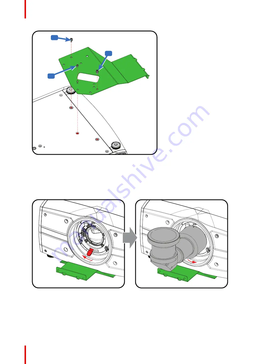
Image 3–27 Mount the bottom plate
3.
Turn in both M6 screws and the M4 screw.
4.
Turn the projector back on its feet.
Slide the lens locking system to the left.
Insert the lens. Make sure the electric contact points (C) on the lens match the contact points on the lens
holder.
Image 3–28 Mount the lens
Summary of Contents for F70 Series
Page 1: ...ENABLING BRIGHT OUTCOMES User Manual F70 Series...
Page 10: ...601 426 15 F70 Series 10...
Page 60: ...601 426 15 F70 Series 60 Lenses Handling and features...
Page 82: ...601 426 15 F70 Series 82 Getting started...
Page 88: ...601 426 15 F70 Series 88 Source menu...
Page 162: ...601 426 15 F70 Series 162 System settings menu...
Page 166: ...601 426 15 F70 Series 166 GUI Status menu...
Page 170: ...601 426 15 F70 Series 170 3D...
Page 171: ...171 601 426 15 F70 Series 13 1 Upgrade procedure 172 Upgrade projector firmware 13...
Page 182: ...601 426 15 F70 Series 182 Technical Specifications...
Page 191: ...191 601 426 15 F70 Series C 1 DMX chart Basic 192 C 2 DMX chart Extended 193 DMX Chart C...
Page 216: ...601 426 15 F70 Series 216 Index...
Page 217: ......


