


P/N 130426 Rev.
D
31
Banner Engineering Corp.
•
Minneapolis, U.S.A.
www.bannerengineering.com • Tel: 763.544.3164
A-GAGE EZ-ARRAY
Instruction Manual
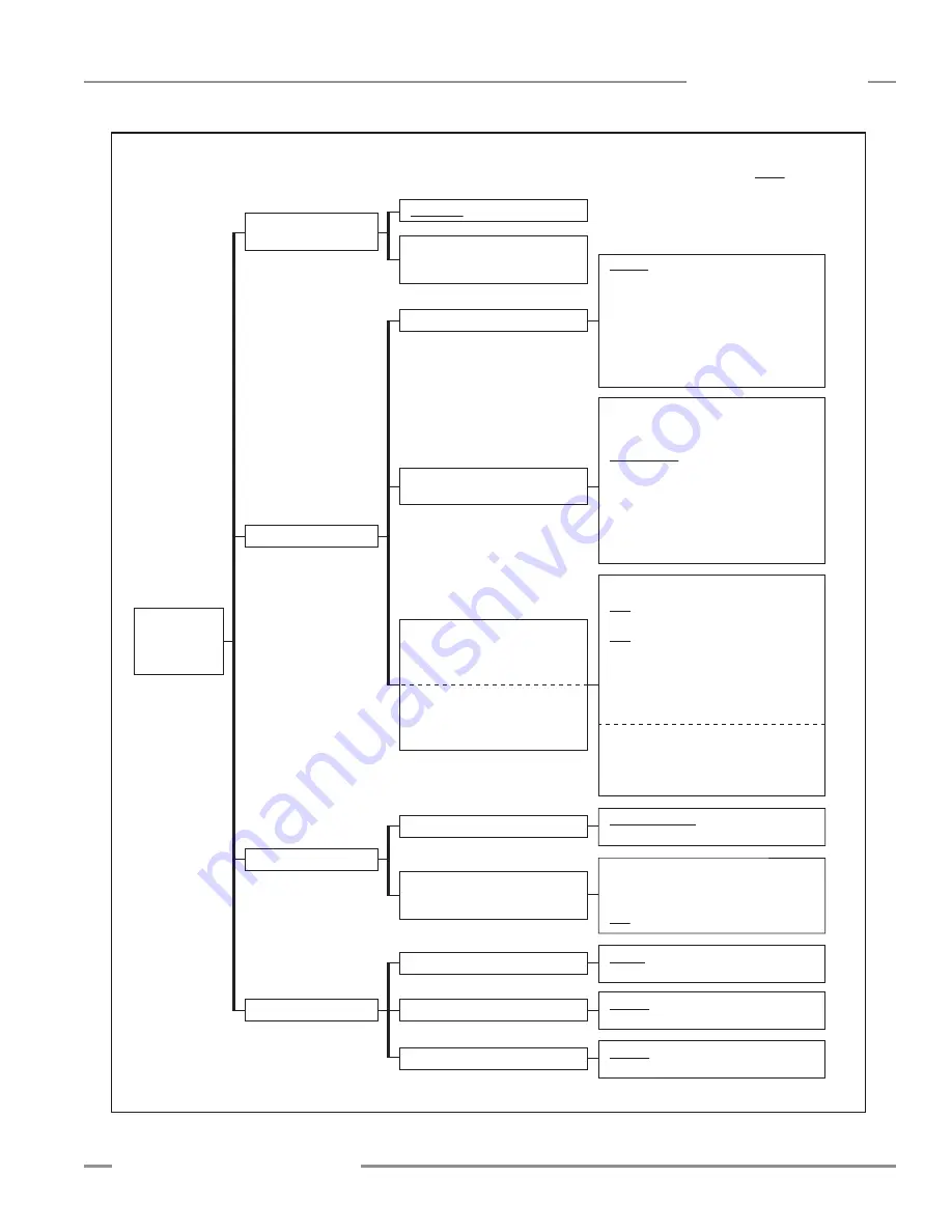
PC Interface
System Configuration –
Configuration Type
Sensor > Setup (Ctrl + S) > System Config View*
(Not available until Connect is performed)
* Use drop-down arrow at right-hand side of the Current View field to quickly move to another view.
A
DIP Switch
Advanced
Verify that Advanced is selected in order
to access other configuration fields
Gain Configuration
User Interface Options
Scan Type
Gain Method
High Excess Gain
Low Contrast
Remote Teach / Gate
Determines the function of the Teach wire
Low Contrast Sensitivity
Available only when
Low Contrast
is selected
Straight
Single Edge
Double Edge – Step 1
Double Edge – Step 2
Double Edge – Step 4
Double Edge – Step 8
Double Edge – Step 16
Double Edge – Step 32
Carpet Nap
Remote Teach
Teach functions can be input
via Teach wire; see Section 1.5
Carpet Nap scan type selected:
Disabled
Carpet Nap
Carpet Edge
Disabled
FBB
Meas 1 default
LBB
TBB
Meas 2 default
TRN
CBB
FBM
LBM
TBM
TBM
CBM
MBB
OD
ID
CFBB
CLBB
Special
(Reserved;
contact Factory)
Alignment/Sensitivity
Gate – Active High
Gate – Active Low
Gate – Rising Edge
Gate – Falling Edge
Disabled
Teach wire has no function;
continuous scan is automatically selected
35%
40%
45%
50%
Display Orientation
Normal
Inverted
15%
20%
25%
30%
Sensitivity Button
Enabled
Disabled
Align / Blanking Button
Enabled
Disabled
System
Configuration
A
Scan Configuration
Measurement 1
The measurement mode mapped
to discrete output 1;
can be any of those at right
Measurement 2
The measurement mode mapped
to discrete output 2;
can be any of those at right
NOTE: Underlined options
designate default settings.
Figure 5-12. PC Interface configuration overview, part 2 of 7


