Banner A-GAGE EZ-ARRAY Instruction Manual Download Page 28

 26 

P/N 130426 Rev. 

D

Banner Engineering Corp. 

• 

Minneapolis, U.S.A.

www.bannerengineering.com  •  Tel: 763.544.3164

A-GAGE EZ-ARRAY 

Instruction Manual

PC Interface

The electronic alignment routine adjusts the emitted light 
level to maximize sensor perfomance. When the system exits 
alignment, the sensor records and stores channel signal 
strength


and blanking information in non-volatile memory until 

electronic alignment is performed again. Perform the procedure 
at installation and again whenever the emitter and/or receiver is 
moved. (For Receiver interface software alignment instructions, 
see Section 4.2.) 

Electronic Alignment Procedure

Note that electronic alignment, once initiated, can not be exited 
without completing the entire routine (there is no “exit without 
save” option). To align the sensor from the PC, press the 

Align 

Sensor

 button on the System Alignment screen. 

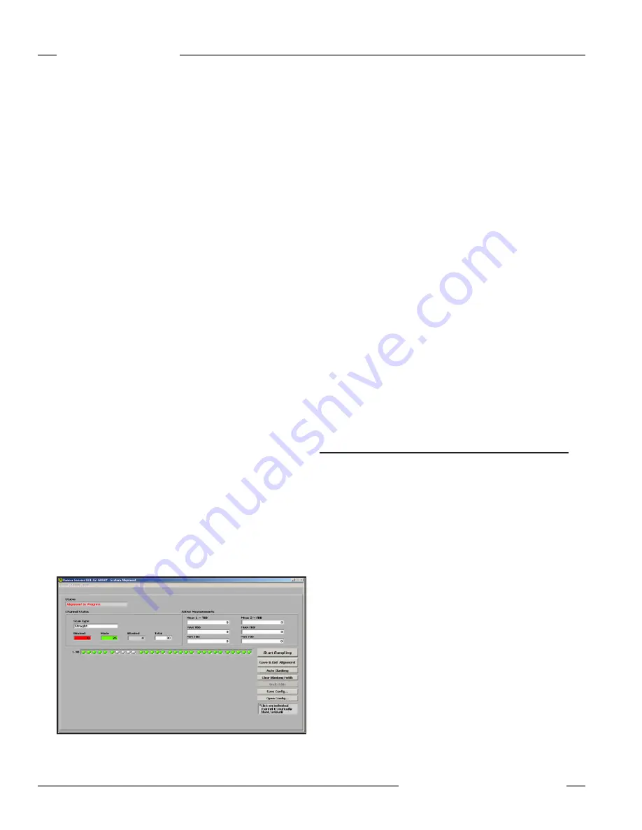
While the sampling is taking place, the Status field of the System 
Alignment screen will read 

Alignment Sampling in Progress

.

When the sensor is aligned and all unobstructed beams are 
detected as made beams, press 

Stop Sampling

. The Status 

window will read 

Alignment in Progress

. When the alignment 

sampling stops, additional options become enabled on the 
Alignment screen: Save and Exit Alignment, Auto Blanking, 
Clear Blanking Fields, Undo Edits (if any blanking changes were 
made), Save Config, and Open Config. 

If necessary, physically adjust the emitter and/or receiver until 
the diagnostic display of the Alignment screen indicates that all 
unblocked beams are made (no red circles). 

If any beams are blocked, they must either be cleared or blanked 
to save the alignment settings (see Figure 5-2).

Click 

Save & Exit Alignment

 to save the gain adjustment 

settings. The sensor will verify that all non-blanked optical 
channels are clear. If some channels are not clear (fail), the 
sensor will not perform the electronic alignment process and 
will retain the previously saved alignment parameters. If all the 
non-blanked optical channels are clear (succeed), the sensor will 
save the new electronic alignment parameters. A message will 
appear that alignment either succeeded or failed. 

If the alignment failed,

 check for objects that may be blocking 

one or more beams, or physically adjust the sensors until all 
beams on the Alignment screen’s diagnostic display are green, 
then repeat the electronic alignment. 


To blank individual channels,

 position the cursor on any of the 

depicted channels (either red or green circles) and click on it. To 
unblank any channel, click on a gray circle.

Click on 

Auto Blanking

 to automatically blank all blocked 

channels and remove blanking from unblocked channels.  
Click on 

Clear Blanking Fields

 to unblank all blanked channels.  

Click on 

Undo Edits

 to remove unsaved channel blanking edits. 

Save Config

Click on 

Save Config

 to save the current set of configuration 

and blanking settings in an .xml file on your computer that can 
then be later retrieved and written to the sensor. In the pop-up 
box, select a storage destination and name the configuration file 
as desired. 

Open Config

Click on 

Open Config

 to retrieve a previously saved 

configuration file. A screen will pop up, allowing you to browse in 
your computer for the file. When you select a new configuration, 
the blanking configuration automatically populates the Channel 
States status fields in the PC interface screens. This applies to 
blanking configuration information only, not to any other settings.

5.6 Configuration Setup

Configuration selections other than blanking and alignment 
adjustment are made to the sensor via the Setup screen. 
The Setup option becomes accessible after a connection is 
established between the PC and the sensor, using the Connect 
option. Refer to Figure 5-12 for an overview of Setup options.

Setup Screen

Selecting 

Setup

 (Ctrl + S) from the Sensor menu launches 

the Setup screen, which has six views: System Config, Analog 
Output Config, Discrete Output Config, Comm Config, Part 
Number and Version Info, and System Diagnostics. The 

Current 

View

 field displays the name of the currently selected view and 

allows quick switching between views; simply click on the arrow 
at the right side of the field to display a drop-down menu of 
alternate views (see Figure 5-9).

When any Setup view is displayed, the options in the Sensor 
menu become:  

 READ All (Ctrl + R) 
WRITE All (Ctrl + W) 
Open Config (Ctrl + O) 
Recent Configs (if any exist) 
Save Config (Ctrl + S) 
Close (Ctrl + Q)

Figure 5-8.  Alignment/Status screen, alignment in progress

Summary of Contents for A-GAGE EZ-ARRAY

Page 1: ...ction profiling and web guiding applications A comprehensive combination of scanning options 14 measurement scan analysis modes 3 scanning methods Selectable beam blanking Selectable continuous or gat...

Page 2: ...continued 13 2 7 Emitter and Receiver Dimensions 14 2 8 Standard Bracket Dimensions 15 3 Installation and Alignment 16 3 1 Mounting the Emitter and Receiver 16 3 2 Mechanical Alignment 17 3 3 Hookups...

Page 3: ...r user interface For more advanced control easy to use PC interface software is available on the included CD to configure the sensors using a PC 1 Overview Installation is easy too The emitter and rec...

Page 4: ...h the light screen Blanking may be set using the receiver interface the teach wire or the PC interface The EZ ARRAY light screen provides a wide selection of sensing and output options including measu...

Page 5: ...in the light screen as well as the total number of beams and totals of beams blocked made and blanked Built in diagnostics can be used to assess emitter and receiver status Outputs In addition to the...

Page 6: ...un Mode L appears on 3 digit display along with number 1 or 2 to designate gain level Toggle Between Gain Settings Number changes from number 1 to 2 back to 1 etc Save Gain Level and Exit When correct...

Page 7: ...t sensitivity is selected or when single edge and double edge scan cannot be used The edge resolution is 5 mm 0 2 When low contrast sensing is selected used when measuring semi transparent objects the...

Page 8: ...s found a binary search is conducted to find the object s bottom edge 5 When the bottom edge is found the sensor continues to step through the array until it finds the next unblocked beam 6 Another bi...

Page 9: ...setting of 15 to 50 When using the receiver interface low contrast sensitivity is always 30 Gain Setting Scan Method EZ ARRAY MODS EZ ARRAY Resolution Low Contrast Straight scan 5 mm 5 mm Single edge...

Page 10: ...n non volatile memory The procedure can be performed using the receiver remote wire the receiver interface or the PC interface see Section 1 5 4 2 or 5 6 The receiver s Alignment push button may be di...

Page 11: ...et in the PC interface in addition to a filter setting to smooth the output and Zero Value to specify the output value when the measurement mode value is zero See Section 5 8 for more information 1 12...

Page 12: ...R900NIXMODQ Receiver EA5R900NUXMODQ Receiver EA5E900Q Emitter EA5R900PIXMODQ Receiver EA5R900PUXMODQ Receiver Current 4 20 mA Voltage 0 10V 900 mm 35 4 180 EA5E1050Q Emitter EA5R1050NIXMODQ Receiver E...

Page 13: ...Cordsets Model Description Pinout MAQDC 815 Straight female connector 8 pin Euro style 5 m 15 long Female Connector Shown MAQDC 830 9 m 30 long MAQDC 850 15 m 50 long Model Description LAT 1 SS Self...

Page 14: ...alues size is tested using a rod Sensor Positional Resolution Straight Scan 5 mm 0 2 Double Edge Scan 2 5 mm 0 1 Single Edge Scan 2 5 mm 0 1 2 6 Specifications 2 4 Accessory Mounting Brackets and Stan...

Page 15: ...imes range from 2 8 to 26 5 ms See Figure 1 8 for all combinations Status Indicators also see Section 1 4 Emitter R ed Status LED ON Red Status OK Flashing at 1 hz Error Receiver 7 Zone Indicators Red...

Page 16: ...7 mm 8 9 260 mm 10 2 199 mm 7 8 150 mm 5 9 EA5 300 379 mm 14 9 412 mm 16 2 351 mm 13 8 300 mm 11 8 EA5 450 529 mm 20 8 562 mm 22 1 501 mm 19 7 450 mm 17 7 EA5 600 678 mm 26 7 704 mm 27 7 650 mm 25 6 6...

Page 17: ...9 4 mm 0 76 38 2 mm 1 50 33 mm 1 30 4 x 45 20 mm 0 79 2 x R 5 mm 0 20 2 x 5 mm 0 20 2 x 15 mm 0 59 2 x 7 mm 0 28 20 mm 0 79 20 mm 0 79 60 mm 20 mm 0 79 17 5 mm 0 69 55 mm 2 17 50 mm 1 97 4 2 mm 0 17 5...

Page 18: ...r and receiver mounting hardware Center mounting brackets must be used with longer sensors if they are subject to shock or vibration In such situations the sensors are designed to be mounted with up t...

Page 19: ...acket hardware See Sections 3 4 and 4 2 for further alignment information Figure 3 2 Sensor mounting mechanical alignment Angled or Horizontal Installations verify that Distance X at the emitter and r...

Page 20: ...nal Inputs Refer to Figures 3 5 and 3 6 for standard hookup information Receiver gray wire The receiver has an input that can be used as a gate input or for remote teach To initiate remote teach align...

Page 21: ...ensor Center each sensor between the noted positions and tighten the end cap mounting screws making sure to maintain the positioning The sensor windows should directly face each other Once optimum opt...

Page 22: ...mode and can be used without the exceptions noted in the other scanning modes Use this scanning mode when using the low contrast sensitivity setting to measure semi transparent materials Double Edge...

Page 23: ...ng outputs from the selected measurement modes Electronic Alignment and Blanking Receiver Interface To initiate the electronic alignment procedure use a small screwdriver to press the Alignment Blanki...

Page 24: ...sensor supply voltage If the error code 2 is removed electrically re align the sensor Section 4 2 If the error code persists contact Banner for further problem solving techniques 3 Reserved for Facto...

Page 25: ...al cable from your receiver to your PC using an RS485 to RS232 adapter such as the model INTUSB485 1 USB serial adapter listed in Section 2 2 Instructions for configuring the adapter are included with...

Page 26: ...Echo Suppression Options are listed To access the Advanced menu select Options Advanced Settings Ctrl U from the Communication Settings menu COM Port selects the computer port used for serial communic...

Page 27: ...see an ongoing realtime display of sensing status Click on Start Sampling the Status window will read Sampling in Progress until Stop Sampling is selected When sampling is not active the Channel Stat...

Page 28: ...alignment failed check for objects that may be blocking one or more beams or physically adjust the sensors until all beams on the Alignment screen s diagnostic display are green then repeat the electr...

Page 29: ...selected Scan Configuration Scan Type Choose between Straight Single Edge or Double Edge Step 1 2 4 8 16 or 32 or Carpet Nap see Section 1 6 for descriptions and scan rates for these scan types Carpe...

Page 30: ...m value and latch this analog value until a reset has occurred see Peak Detect Reset Peak Detect Reset auto or external communication specifies the method by which the analog output peak detect is re...

Page 31: ...sed to smooth the discrete output response Each discrete output can respond after each sensor scan or the response time can be increased by increasing the demodulation Increasing the demodulation incr...

Page 32: ...current sensor pair so that other sensors on the network can be connected Options DPB1 No Echo Suppression Echo Suppression Status Read only indication of current sensor communication status If DPB1...

Page 33: ...e Step 8 Double Edge Step 16 Double Edge Step 32 Carpet Nap Remote Teach Teach functions can be input via Teach wire see Section 1 5 Carpet Nap scan type selected Disabled Carpet Nap Carpet Edge Disab...

Page 34: ...ement Model Selected Either discrete output Normally Open Default for output 1 Normally Closed Default for output 2 Alarm Health Status Mode Selected Discrete output 2 only D02 Type Available for outp...

Page 35: ...ly indication Emitter Power Read only indication Error Code Read only indication DIP Switch S1 Read only indication DIP Switch S2 Read only indication DIP Switch S3 Read only indication DIP Switch S4...

Page 36: ...HIGH byte LOW byte Request Function Code 1 byte 0x03 Starting Address 2 bytes 0x0000 to 0xFFFF Quantity of Holding Registers 2 bytes 0x0001 to 0x007D Response Function Code 1 byte 0x03 Byte Count 1 b...

Page 37: ...40001 is accessed by writing address 40001 0x9C41 directly i e the starting address is not an offset Data is packed as two bytes per register For each register the data is sent in big endian order HI...

Page 38: ...channels 1 5 9 6 Double Edge Step 8 Scanning for Edges of up to 3 objects fires channels 1 9 17 7 Double Edge Step 16 Scanning for Edges of up to 3 objects fires channels 1 17 33 8 Double Edge Step 3...

Page 39: ...6 register address 40003 is set to the two byte value of 0x0003 3 decimal General Configuration The General Configuration contains the general settings for the EZ ARRAY Table A 6 General Configuration...

Page 40: ...Object 1 Last Beam Blocked 17 O2 FBB Object 2 First Beam Blocked 18 O2 LBB Object 2 Last Beam Blocked 19 O3 FBB Object 3 First Beam Blocked 20 O3 LBB Object 3 Last Beam Blocked 21 CARPET NAP Carpet Na...

Page 41: ...response is 24 scans for 98 of signal Table A 23 NULL Output Analog Outputs 1 and 2 Range Description 0 4095 Minimum DAC value of Analog Output MUST be SPAN Output Table A 24 SPAN Output Analog Outpu...

Page 42: ...er Name 40040 LOW BYTE Config 40040 HIGH BYTE RESERVED 40041 Demodulation Count 40042 Hysteresis LOW 40043 Hysteresis HIGH 40044 Threshold LOW 40045 Threshold HIGH A 3 Input Registers A 3 1 Active Mea...

Page 43: ...Address 41 Slave Address 41 Function 04 Function 04 Starting Address HIGH Byte 77 Byte Count 32 Starting Address LOW Byte 24 Register 30500 HIGH Byte 00 Quantity of Registers HIGH Byte 00 Register 305...

Page 44: ...n the EZ ARRAY Each register represents 16 channels Table A 38 Channel States Model Input Register Address MASK Member Name 150 1800 mm 30003 LOW BYTE Channel 1 8 30003 HIGH BYTE Channel 9 16 30025 LO...

Page 45: ...30026 Number of Emitter Channels 30027 Emitter First Bad Channel 30028 Number of Receiver Channels 30029 RESERVED 30030 LOW BYTE DIP Switch 30030 HIGH BYTE ERROR Code 30031 LOW BYTE RESERVED 30031 HIG...

Page 46: ...tter Version Info Input Register Address MASK Member Name 31000 Receiver Part Number 31001 31002 LOW BYTE Receiver Version 31002 HIGH BYTE RESERVED 31003 Emitter Part Number 31004 31005 LOW BYTE Emitt...

Page 47: ...hat runs unobstructed from the emitter to the receiver same as a made or unblocked beam Excess Gain A measurement of the amount of light falling on the receiver from the emitter over and above the min...

Page 48: ...R ARISING UNDER COURSE OF PERFORMANCE COURSE OF DEAL ING OR TRADE USAGE This Warranty is exclusive and limited to repair or at the discretion of Banner Engineering Corp replacement IN NO EVENT SHALL B...

Reviews: