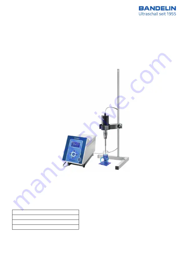
Ultrasonic homogeniser HD 4100
7
Ultrasonic homogenisers
51376-010 GB/2020-10
User Instructions
Valid for:
HD 4050
Volume:
0.5 ml - 100 ml
HD 4100
2 ml - 200 ml
HD 4200
5 ml - 1000 ml
HD 4400
100 ml - 3000 ml
Page 1: ...homogeniser HD 4100 7 Ultrasonic homogenisers 51376 010 GB 2020 10 User Instructions Valid for HD 4050 Volume 0 5 ml 100 ml HD 4100 Volume 2 ml 200 ml HD 4200 Volume 5 ml 1000 ml HD 4400 Volume 100 m...
Page 2: ...ment the original version will take precedence BANDELIN accepts no responsibility or liability for damages caused by improper handling or usage contrary to the intended purpose The documentation was p...
Page 3: ...rmity will no longer be valid If Service is required please contact the specialist dealer in charge or the manufacturer Symbols used Symbol Significance Explanation Danger Identifies information that...
Page 4: ...tion 13 2 1 Scope of delivery 14 2 2 Set up assembly 14 2 3 Start up 15 3 Operation 15 3 1 Operating elements 15 3 1 1 Turning the homogeniser on o 16 3 1 2 Explanation of the display fields 16 3 2 Se...
Page 5: ...r vessels and accessories pertaining to the medical field 33 5 3 Warehousing storage 33 6 Maintenance and repair 34 6 1 Maintenance 34 6 2 Functional checks 34 6 2 1 Testing the ultrasonic converter p...
Page 6: ...s The type specification and serial number are found on the type plate Product features Ultrasonic generator 1 in low maintenance robust plastic housing with connections for the ultrasonic converter t...
Page 7: ...probes are mounted on the ultrasonic converter These work as mechanical transformers and enable a multiple mechanical amplification of the ultrasonic amplitude at the tip 1 2 Purpose SONOPULS ultrason...
Page 8: ...ntial free contact foot switch TS 8 optional Interface RS 232 Degree of protection IP 30 according to DIN EN 60529 Device specific Generator GM 4200 GM 4400 Power 2 maximum 50 100 200 W 3 200 400 W3 U...
Page 9: ...o 31 C 80 Permissible relative humidity up to 40 C 50 Permissible ambient temperature 5 to 40 C Altitude up to 2000 m above sea level No condensation allowed Only for indoor operation Specifications f...
Page 10: ...Remote control connector 4 External data protocol Status inquiry Full device control RS 232 interface a Remote control connector Contact assignment and functional description of the remote control co...
Page 11: ...chnical programs required for communication is the responsibility of the operator and is not supported by the manufacturer The manufacturer only guarantees the proper functioning of the interface The...
Page 12: ...implant manufacturer Operation Observe ambient and set up conditions see chapter 1 4 Determine the mains voltage before connecting the ultrasonic generator Only connect the ultrasonic generator to a g...
Page 13: ...ation portable or mobile HF communication systems in the vicinity of the homogeniser should be turned o operation may be disrupted Damages If damage to the homogeniser is detected do not connect the u...
Page 14: ...orresponding ultrasonic converter Other standard booster horns are mountable To do so see instructions in chapter 4 4 Screw the delivered probe to the standard booster horn see chapter 4 3 1 Position...
Page 15: ...6 010 GB 2020 10 1 electronic GmbH Co KG Heinrichstra e 3 4 12207 Berlin Deutschland info bandelin com 2 3 Start up Check the positioning of the ultrasonic converter in the holder Check the firm posit...
Page 16: ...splay is only visible when a temperature sensor is connected Prog 3 Ampl 10 Time set 00 01 00 elapsed 00 00 00 Pulsation off Energy 0 000 kJ The mains switch can also be used for powering o The poweri...
Page 17: ...peration is ended by pressing the START STOP key a Setting continuous operation non stop SET Prog 1 Ampl 10 Time set 00 01 00 elapsed 00 00 00 Pulse 4 0s 4 0s Stop at 0 C C Energy 0 000 kJ Time set 00...
Page 18: ...us sound by hand key it is possible to pulse manually with the key on the ultrasonic converter Ultrasound operation will be active as long as the key on the ultrasonic converter is pressed a Setting t...
Page 19: ...g 3 Ampl 10 Time set 00 00 15 elapsed 00 00 00 Pulsation off Stop at 0 C C Energy 0 000 kJ Stop at 0 C C Example SET Prog 3 Ampl 10 Time set 00 00 15 elapsed 00 00 00 Pulsation off Temperature C Energ...
Page 20: ...n is restored if no device fault or other cause is present The set value is o In order to activate the function set the parameter to start using the arrow keys and then press the START STOP key See ch...
Page 21: ...hether the accumulated energy Energy or the current ultrasonic frequency frequency is displayed Sequencing batch mode With this function batch mode on there is an option for processing previously grou...
Page 22: ...rogram No 1 Amplitude 10 Time set 00 01 00 Pulse 4 0s 4 0s Temp alarm at 0 load store quit start No 1 The START STOP key is used to exit memory management and return to stand by mode 3 4 Batch operati...
Page 23: ...resulting control processes a di erence between the target and the actual value as well as a fluctuating display may occur The amplitude and the power can be changed at any time during ultrasound oper...
Page 24: ...ducing emulsions the probe should be immersed to the level of the interface between the liquids to be mixed Do not use combustible solvents in open reaction vessels since the operating safety of the h...
Page 25: ...hen immersing oscillating probes Step 5 Remove the sample After sonication the probe must be removed from the medium Leaving them in the sonicating medium for a longer time can cause damage to the pro...
Page 26: ...100 15 150 20 200 20 200 Max amplitude mSS 260 245 195 155 130 82 80 Max setting 90 100 100 100 100 100 100 GM 4200 with UW 200 and SH 200 G Probe TS 103 TS 104 TS 106 TS 109 TS 113 TT 213 TS 216 TS 2...
Page 27: ...sitive to shock Before mounting the probes the ultrasonic generator must be turned o and the ultrasonic converter must be disconnected from the ultrasonic generator The mounting surfaces 5 must be tho...
Page 28: ...horn SH 100 G or SH 200 G First carefully wipe the mating surfaces of the standard booster horn and of the titanium flat tip ensure clean mating surfaces Screw on the titanium flat tip by hand Apply s...
Page 29: ...refully wipe the mounting surfaces of the standard booster horn and the probe ensure clean mounting surfaces Screw on the probe by hand Lay the probe on an approx 20 mm thick base so that it does not...
Page 30: ...0 G onto UW 200 at the time of delivery Before mounting the standard booster horns the ultrasonic generator must be turned o and the ultrasonic converter must be disconnected from the ultrasonic gener...
Page 31: ...imilar on the threaded portion of the bolt and press lightly in the direction of the arrow this will prevent the bolt from turning any further when the standard booster horn is screwed on Screw the st...
Page 32: ...If abrasion of material due to erosion or post processing exceeds a value of approx 1 mm or if there is no power display on the generator the probe is non resonant and can no longer be used Reconditi...
Page 33: ...mitting surfaces see chapter 5 1 Wear Therefore the sonicating parts such as the standard booster horn probe vessels and accessories should be disinfected and cleaned after every use and dismounted fo...
Page 34: ...conducted while the probe is acoustically coupled i e the probe should be immersed in the sonicating medium SET START STOP probe check off scan frequency off contrast 22 operating mode ampl 01 02 2014...
Page 35: ...n probe on the GM The GM should then automatically recognize which USC has been plugged in 002 Frequency setting not possible Perform frequency scan If the error occurs again contact BANDELIN 003 No p...
Page 36: ...trasonic converter to the standard booster horn or from the horn to the probe not secure Using the tool supplied separate parts from one another clean the surfaces and firmly screw together once again...
Page 37: ...tified the homogeniser may not be used In such a case please contact the supplier or the manufacturer in writing and use the enclosed questionnaire BANDELIN electronic GmbH Co KG Heinrichstrasse 3 4 1...
Page 38: ...e receipt of the package in order to protect our employees The form can be downloaded from the Internet as a PDF file www bandelin com downloads 6 4 2 Software version display In some cases it may be...
Page 39: ...ltation Website 49 0 30 768 80 0 www bandelin com 7 1 Required accessories In order to mount dismount standard booster horns or probes only use the tools specified in appendix A 7 2 Optional accessori...
Page 40: ...for this ultrasound application 9 Taking the unit out of service The device must be disposed of appropriately not with household waste Disposal must be conducted in accordance with the Waste Electrica...
Page 41: ...3 Contamination 25 33 Continuous operation 8 16 17 20 D Damages 8 12 13 25 Decontamination 38 Degree of protection 8 9 Disinfection 33 Dismounting 12 27 28 29 30 39 E Energy 7 8 16 17 23 Error message...
Page 42: ...2 34 35 36 39 Product features 6 Product information 3 26 31 Protection class 8 Pulsation time 8 16 Purpose 7 9 R Reconditioning probe 32 Remote control 10 Remote control sleeve 6 10 Remote operation...
Page 43: ...ltrasonic converter 6 7 8 9 10 12 13 14 15 16 18 20 21 23 24 27 30 31 33 34 35 36 37 39 40 Ultrasonic frequency 8 Ultrasonic generator 6 7 8 12 13 15 20 27 30 40 Ultrasound operation 8 10 17 18 19 23...
Page 44: ......
Page 45: ...er Type Use Spanner MS 10 long To mount dismount probes UW 50 SH 100 G SH 200 G Spanner MS 22 To mount dismount probes to SH 400 G Sickle spanner HS 25 28 long To to hold the UW 50 firmly in order to...
Page 46: ...Important The Instructions for Use in this and other languages as well as further information can be found on the enclosed CD...