www.balluff.com
41
IO-Link integrates conventional and intelligent actuators and sensors into automation systems.
Mixed use of traditional and intelligent devices is possible with no additional expense.
IO-Link is intended as a communications standard below the traditional fieldbus level. Fieldbus-
neutral IO-Link transmission uses existing communications systems (fieldbuses or Ethernet-
based systems).
The actuators and sensors are connected in point-to-point connection using conventional uns-
hielded cables.
IO-Link devices can send application-specific parameters and data (e.g. diagnostics data) using
a serial communication procedure. Flexible telegrams are possible for sending larger quantities of
data. Communication is based on a standard UART protocol with 24V pulse modulation. Only
one data line is used for communication. This carries both the controller telegram as well as the
device telegram. This means that conventional 3-conductor physics is possible.
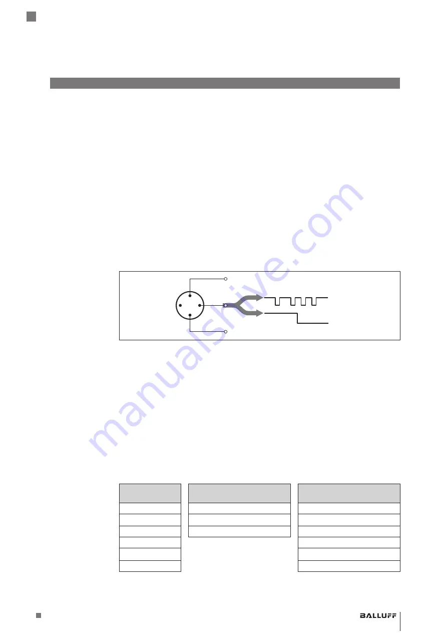
IO-Link supports both communication mode as well as standard IO mode (SIO). Standard IO
provides a switching signal on the communication line, as is used by normal binary switching
sensors. This mode is only possible with devices using 3-conductor connection technology. SIO
mode is not supported by BIS M-IO-Link devices.
Figure 33: Three-conductor physics of the IO-Link
In communication mode, the BIS M IO-Link device operates with frame type 2. In this transmis-
sion type, up to 32 bytes of process data is sent in both directions per frame and 2 bytes of
demand data is sent per frame. Process data is the application-specific data; demand data may
contain parameters, service or diagnostic data.
The IO-Link protocol provides a process data container 32 bytes in size. Addressing occurs in
the command byte, which is sent by the IO-Link master. When process data is sent, addressing
is directly to the subindices 00
hex
… 1F
hex
.
The BIS M-4_ _-045-... processes 10 bytes of input and 10 bytes of output data (input buffer/
output buffer). The process data is mapped to the first 10 bytes of the process data container
(subindices 00
hex
…09
hex
). The BIS M-4_ _-072-... processes 32 bytes of process data (subindi-
ces 00
hex
…1F
hex
).
IO-Link protocol
Subaddress
BIS M-4_ _ -
45
... IO-Link device
Subaddress
BIS M-4_ _ -
72
... IO-Link device
Subaddress
00
hex
00
hex
00
hex
...
...
...
09
hex
09
hex
09
hex
0A
hex
0A
hex
...
...
1F
hex
1F
hex
6.1 Digital Point-to-
point Connection
Three-conductor
physics
Communication
mode
6.2 Process Data
Container
6
IO-Link basics
BIS M-4 _ _ IO-Link Device
Read/Write Device
Summary of Contents for BIS M-4 045 0 07-S4 Series
Page 2: ...www balluff com...
Page 4: ...www balluff com www balluff com...
Page 67: ...www balluff com 65 BIS M 4_ _ IO Link Device Schreib Leseger t...
Page 70: ...www balluff com www balluff com...
Page 133: ...www balluff com 65 BIS M 4_ _ IO Link Device Read Write Device...
Page 135: ...BIS M 4_ _ 045 _0_ 07 S4 BIS M 4_ _ 072 _0_ 07 S4...
Page 136: ...www balluff com www balluff com...
Page 141: ...www balluff com 7 1 BIS CRC DPP EMC LSB MSB PC SIO IO SPDU PLC TCP 1 6 1 7 BIS M 4_ _ IO Link...
Page 142: ...8 BIS M 4xx_ _ BIS M EMC A IO Link BIS M 4_ _ 24 A 2 1 2 2 2 3 2 BIS M 4_ _ IO Link...
Page 152: ...18 3 IO Link M12 A 1 24 V 2 3 GND 4 C Q 2 2 2 IO Link IO Link RC 3 2 BIS M 4_ _ IO Link...
Page 199: ...www balluff com 65 BIS M 4_ _ IO Link...
Page 201: ......


