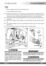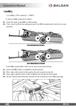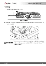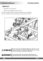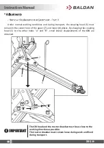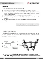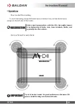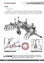
Under normal working conditions and during transport, the coupling head (5) must
remain in the center hole of the upper (7) and lower (8) plates. By changing the coupling
head (5) to the other holes "A" and "B", small lateral displacements of the
CRI
are
obtained.
The CRI head and the tractor drawbar must be as close to the
working direction as possible.
The tractor drawbar must remain loose during work and
fixed
during transport.
IMPORTANT
7
5
8
“A”
“B”
Instruction Manual
Summary of Contents for CRI
Page 1: ...Drag Type Offset Disc Harrow Remote Control CRI 12 30...
Page 2: ......
Page 59: ...InstructionManual...
Page 62: ......
Page 64: ......
Page 67: ......

