38
38
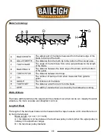
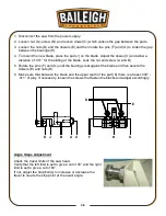
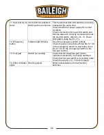
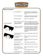
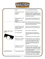
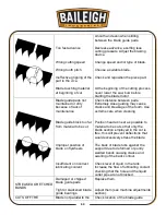
1. Disconnect the saw from the power supply.
2. Loosen nut (A), screw (B), and loosen dowel (C) which widens the gap between the pads.
3. Loosen the nuts (D) and the dowels (E) and then rotate the pins (F) and (G) to widen the gap
between the bearings (H).
4. To mount the new blade, place the pad (J) on the blade. Adjust the dowel (C) and allow a
distance of .001” for the sliding of the blade. Lock the nut and screw (A and B).
5. Rotate the pins (F) and (G) until the bearings rest against the blade and then secure the
dowels (E) and nuts (D).
6. Make sure that between the blade and the upper teeth of the pad (K
) there is at least .008” -
.011” of play. If necessary, loosen the screws that fasten the blocks and adjust accordingly.
Angle Stops Adjustment
Check the travel limits of the saw head.
Verify that the left limit is set to give a cut of 45° and the right
limit is set to give a cut of 60°.
If not, adjust the stop bolt(s) to increase or decrease the
travel to create the stop point at the exact angle.
A
B
C
D
E
G
H
F
J
K
Summary of Contents for BS-350SA
Page 17: ...14 14 OVERALL DIMENSIONS...
Page 18: ...15 15 GETTING TO KNOW YOUR MACHINE I H G F E D C B A T P O Q S M N U L R V J K T...
Page 36: ...33 33...
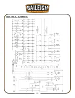
Page 49: ...46 46 ELECTRICAL SCHEMATIC...
Page 58: ...55 55 NOTES...
Page 59: ...56 56 NOTES...


