24
24
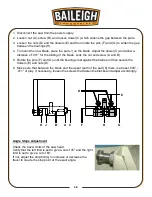
Install the splash tray
The splash tray (V) fits onto the sidewall of the base as
shown in the photo at right. (Customer to determine best
location as it can change based upon cutting angles.)
Mounting the stop bar assembly
Locate the mounting hole on the right side of the vise
block.
Back out the set screw to allow insertion of the
graduated rod. (make sure scale can be easily read
by the operator).
Tighten setscrew until rod is tight.
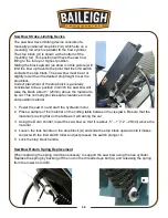
Positioning the “E”-Stop / footswitch pedestal
Locate the pedestal at the front of the saw near the base operating controls
as shown.
The operator should stand in front of the saw while cutting as a safety
precaution, and to have access to the base controls for blade speed and
bow descent speed. This also keeps the two E-Stop switches close.
The foot pedestal can be repositioned as needed to be within easy reach of
the operator when loading and unloading material as well as when cutting
various angles.
V
setscrew
Summary of Contents for BS-350SA
Page 17: ...14 14 OVERALL DIMENSIONS...
Page 18: ...15 15 GETTING TO KNOW YOUR MACHINE I H G F E D C B A T P O Q S M N U L R V J K T...
Page 36: ...33 33...
Page 49: ...46 46 ELECTRICAL SCHEMATIC...
Page 58: ...55 55 NOTES...
Page 59: ...56 56 NOTES...


