39
39
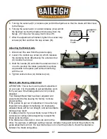
Saw Bow Stroke-Limiting Device
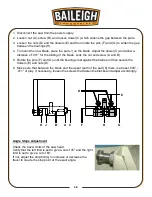
The saw bow travel limiting device consists of a
manually positioned stop block (A) which sits on a
mounting rod which is parallel to the bow cylinder.
The stop block (A) is shown at the bottom of the
mounting rod. This position will have the saw bow
lifting to the full up or highest position.
Sliding the block upward (as shown in this picture) will
limit the bow up travel to the point that the limit switch
contacts the stop block. The saw bow must be at or
slightly lower than the desired stop height to set the
stop block.
Correct placement of the stop block is generally
considered to be a position in which the saw bow will
raise the blade about 1” (25mm) above the material to
be cut. This normally provides safe clearance to load
and position material.
1. Power the saw On and start the hydraulic motor.
2. Place a sample of the material on the cutting table between the vise jaws. Be sure that the
material is resting flat on the table as it will during the cut.
3.
Using the Down control, lower the saw bow so that it is about .5” – 1” (12 – 25mm) above the
material.
4. Loosen the lock handle on the stop block (A) and slide the stop block upward until it makes
contact with the limit switch roller and just presses the switch plunger in.
5. Lock the stop block handle.
Saw Bow Return Spring Replacement
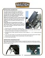
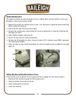
When replacing the spring it will be necessary to support the saw bow using the rise cylinder.
Replace the spring by backing off the nut on the threaded eye bolt (A) and releasing the spring
from the lower tie rod (B).
B
A
A
Summary of Contents for BS-350SA
Page 17: ...14 14 OVERALL DIMENSIONS...
Page 18: ...15 15 GETTING TO KNOW YOUR MACHINE I H G F E D C B A T P O Q S M N U L R V J K T...
Page 36: ...33 33...
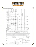
Page 49: ...46 46 ELECTRICAL SCHEMATIC...
Page 58: ...55 55 NOTES...
Page 59: ...56 56 NOTES...


