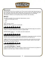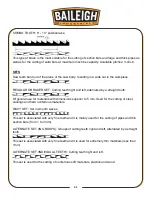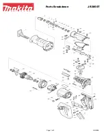
16
16
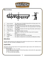
A
Vise Hand Wheel
Turning hand-wheel opens and closes the vise for course
adjustment to within .5” to .75” (12.7 – 19mm) of clamping
the material.
B
Vise Clamping Cylinder
During normal operation, hydraulic pressure will extend the
cylinder to clamp the material for the cut. After the cut, the
vise will open automatically,
C
Vise
Holds front and rear jaws for clamping
D
Blade Tension Hand
Wheel
For applying and releasing blade tension
E
Blade Tension Gauge
Reads tension in Kgs/cm2. For this saw the blade tension
should be 140Kgs/cm2
F
Blade Break Microswitch Shuts down saw if blade breaks or if the tension is too low.
G
Front Blade Guide
Assembly
Guides the blade into the material during the cut. This
guide is adjustable and should be set as close to the
material without interfering with the material.
H
Back Blade Guide
Assembly
This guide is a fixed position and is intended to guide the
blade as it exits the cut path.
I
Control Box
Houses the operator controls
J
Bow Cylinder
The cylinder is used to provide the down and up force to
lower and lift saw bow.
K
Saw Bow Limit Switches.
The limit switches which control the down travel and the up
travel of the saw bow. The down limit switch has limited
adjustment to stop the down travel when the blade has
completed the cut. The up-limit switch has adjustment to
allow the bow to raise about 1: (25mm) above the table to
the full up position as desired.
L
Motor/Gearbox
Drives the saw blade
M
Coolant Pump
Recirculates blade coolant to the blade cutting area.
N
Hydraulic System
The reservoir, motor, pump, and valve assembly which
supplies and controls the hydraulics to operate the
clamping and saw bow cylinders.
O
Miter Lock Lever
Tightens and loosens the saw head to allow the head to
swivel to the desired angle.
P
Angle Indicator
Shows angular cutting degrees. 0 - 60°R, 0 - 45°L
Q
Saw Stand
Supports the saw assembly.
R
Vise Slide Lock
Locks vise in the table slideway. Used with the Track Lock.
S
Flow Regulator
This flow control will allow control of the speed that the ow
descends into and through the cut.
T
E-Stop (Emergency Stop) Shuts down saw in emergency situation
U
Track Lock
Allows vise to slide in track. Used with the Vise Slide Lock.
Summary of Contents for BS-350SA
Page 17: ...14 14 OVERALL DIMENSIONS...
Page 18: ...15 15 GETTING TO KNOW YOUR MACHINE I H G F E D C B A T P O Q S M N U L R V J K T...
Page 36: ...33 33...
Page 49: ...46 46 ELECTRICAL SCHEMATIC...
Page 58: ...55 55 NOTES...
Page 59: ...56 56 NOTES...


