48
48
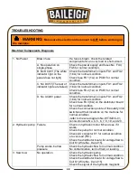
TROUBLESHOOTING
Electrical Components Diagnosis
1. No Power
Blown fuse
If a fuse is blown, check the related
components for an over-load or short-circuit.
A. No operation on
single-phase
Check the power supply and fuses No. FU4,
FU5 for normal condition.
B. No DC24V (The white
indicator light on the
panel does not light)
Check the transformer’s inputs FU1 and FU2
(1.6A) for normal condition.
Check fuse FU1 (1A) on PCB1 for normal
condition.
C. No DC5V (The rest of
indicator lights are failed.)
Check the transformer’s inputs FU1 and FU2
(1.6A) for normal condition.
Check fuse FU2 (1A) on PCB1 for normal
condition.
D. No AC24V power
Check the transformer’s inputs FU1 and FU2
(1.6A) for normal condition.
Check fuse FU3 (6A) on the distributor board
for normal condition.
Check the connection points of the safety limit
switches at their locations on the machine for
normal condition
-refer to the wire diagram No: WT/M3/C-01,
connection wire No. 4, 5, 6, 7, 8, 19, and 20.
2. Hydraulic pump Failure
Check on hydraulic motor M1 and see if it
works.
Check the pump for normal condition.
Check AC contactor K1 for normal condition
or over-load (FS1).
Check the distributor board for voltage flow to
Coil K1 (Wire No. 9 and 15).
Pump works, but low
pressure
Check the hydraulic flow for normal condition
No contamination, lack of fluid, or leaking.
3. Saw bow
No operation
Check the hydraulic pump.
Check the hydraulic flow for normal condition.
Check the distributor board for voltage flow to
Coil K1 (Wire No. 9 and 15).
Check the signal of the hydraulic magnetic
WARNING:
Make sure the electrical disconnect is OFF before working on
the machine.
Summary of Contents for BS-350SA
Page 17: ...14 14 OVERALL DIMENSIONS...
Page 18: ...15 15 GETTING TO KNOW YOUR MACHINE I H G F E D C B A T P O Q S M N U L R V J K T...
Page 36: ...33 33...
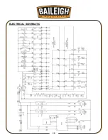
Page 49: ...46 46 ELECTRICAL SCHEMATIC...
Page 58: ...55 55 NOTES...
Page 59: ...56 56 NOTES...


