background image

102 


User’s Manual—SNAP™ 700 Printer


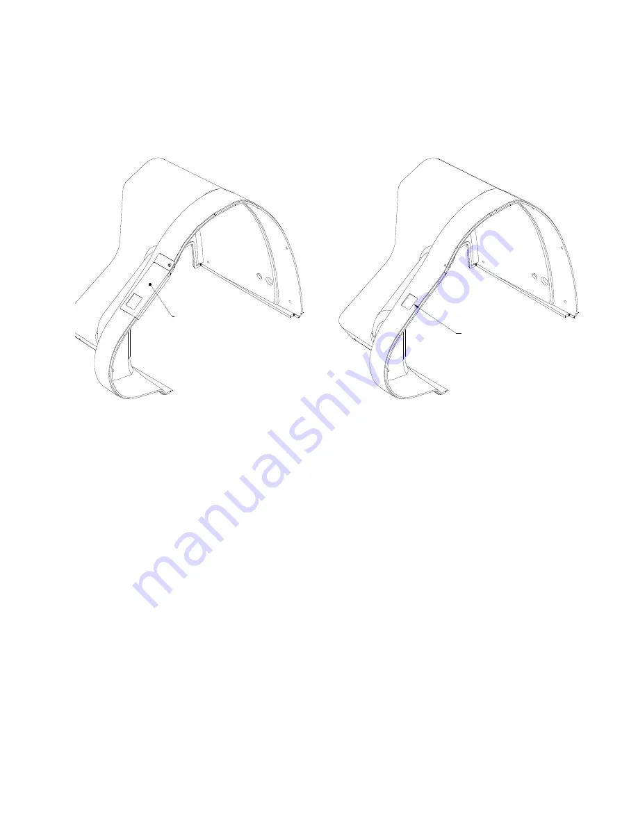
13.  Using the supplied Template, scribe a cutout line on the Rear Cover. 


SCRIBE TEMPLATE

SCRIBE AND REMOVE
THIS MATERIAL


14.  Remove the material within this scribed line.  Drill corners and use a Dremel Tool or 

Small Saw. 

15.  Slide Cover onto Printer.  The Cutout should be over the Control Plate on the Sensor.  

The Sensor may require both horizontal and vertical readjustment to fit below the cutout. 

16.  Reattach the Rear Cover.  Reconnect Stacker connection. 

17.  When ready to use a sense mark format, program the Sensor per instructions provided 

with the Sensor. 


5. Programming the Contrast Sensors 

 
There are two optional contrast sensors available for the SNAP 700 printer.  620006-1 is the 
standard contrast sensor.  It works well in most situations where there is significant contrast 
between  the  material  background  and  the  sense  mark.    In  situations  where  there  is  less 
contrast  between  the  material  and  the  sense  mark,  or  the  material  and  sense  mark  are  of 
similar colors, the 620007-1 Color Contrast Sensor may be required. 
 
Both  sensors  have  to  be  “taught”  the  difference  between  the  material  background  and  the 
sense mark.  The procedures are similar, and are described below. 


Summary of Contents for SNAP 700

Page 1: ...Operator s and Service Manual Avery Dennison SNAPTM 700 Printer SNAPTM 700 RFID Printer 621398 Rev 4 5 3 14 2014 Avery Dennison Corp All rights reserved 028028...

Page 2: ...vice may not cause harmful interference and 2 this device must accept any interference that may cause undesired operations This Class A digital apparatus meets all requirements of the Canadian Interfe...

Page 3: ...nter Configurations 16 2 5 Setting up the Printer 17 2 5 1 Attaching the Stacker 17 2 5 2 Checking the Main Fuse Configuration 18 2 5 3 Installing the Power Cord 19 2 5 4 Installing the PC Interface C...

Page 4: ...Darkness 41 4 2 Adjusting the Stacker 41 4 2 1 Stacker Position 42 4 2 2 Toggle Switch 42 4 2 3 Stacker Angle 42 4 2 4 Platform 43 4 3 Virtual Control Panel 44 4 3 1 Introduction 44 4 3 2 Changing Pr...

Page 5: ...nife Assembly 62 5 4 1 Removing and Replacing the Knife Assembly 63 5 4 2 Adjust the Knife Home Position 66 5 5 Rubber Roller Replacement 66 6 0 SERVICE ADJUSTMENTS 67 6 1 Stock Web Guide Position 67...

Page 6: ...s 620006 620007 98 Installation Procedure 98 5 Programming the Contrast Sensors 102 Programming the Contrast Sensor 103 Programming the Color Contrast Sensor 104 6 Instructions for Factory Field Insta...

Page 7: ...ly RFID 126 Top Print Head Assembly 127 Bottom Print Head Assembly 128 Print Head Assembly 129 Platen Roller Assembly 130 Ink Arbor Assembly 131 Ink Unwind Rewind Motor s Assembly 132 Drive Assembly 1...

Page 8: ...User s Manual SNAP 700 Printer Addendum II Short Feed 147 Short Feed O Ring Replacement 147 Short Feed Assembly 149 Short Feed Part List 150 Revision Record 152...

Page 9: ...easy to use quick reference guide It contains procedures for receiving handling set up installation operation and maintenance of the SNAP 700 printer Please read this section of the manual to familia...

Page 10: ...high 1 8 m x 76 cm x 81 cm The host PC if used and any printer options will increase the required area AVERY DENNISON recommends using an industrial type worktable Refer to Figure 1 below The SNAP 700...

Page 11: ...printing software supports the new virtual control panel feature when using the SNAP 700 printer PCMate features higher communication speeds of the SNAP 700 Finally it can deliver firmware upgrades fr...

Page 12: ...oper replacement and disposal Call 1 800 543 6650 Warning There are hazardous moving parts at the print head station Keep hair loose garments jewelry and fingers away 2 2 Receiving The SNAP 700 printe...

Page 13: ...g material and moisture 4 It requires 2 people to remove the printer from the carton 5 Position your hands in the cardboard cutout as above Carefully lift it out of the box Lift the printer from the b...

Page 14: ...tems listed above are missing contact AVERY DENNISON for further instructions In the U S A call 937 865 2123 select option for Customer Service Outside the U S A please contact your local AVERY DENNIS...

Page 15: ...the Arbor to accommodate stocks ranging from inch 5 inches 12 7 mm 127 mm wide The arbor auto centers the stock through the printer Metal fingers extend to hold the supply roll in place This allows b...

Page 16: ...You can adjust it to accommodate a variety of label stocks and short or long labels Once the stacker reaches the bottom the printer will stop indicate the stacker is full and allow you to remove the...

Page 17: ...beyond the stock size to be run NOTE Be sure to slide the top of the stacker behind the Nip Roller stripping plate 3 With the power off connect the stacker cable extending from the bottom of the stac...

Page 18: ...hes the appropriate voltage for your location you can proceed with setting up your printer 2 If the line voltage does not match the voltage for your location contact your local AVERY DENNISON supplier...

Page 19: ...the printer just below the power switch see Figure 5 2 Plug the power cord into the AC power entry receptacle 2 5 4 Installing the PC Interface Cable If you will be using your SNAP 700 printers with...

Page 20: ...ing directly from a mainframe when using the RS232 interface and AVERY DENNISON s command language PCL 2 5 6 Attaching the Unwind Assembly Figure 6A Unwind Assembly Installation The unwind assembly is...

Page 21: ...at There are two test formats built into the printer These are selected using the Option Menu System The steps below describe how to select one of the test formats For more information on the Option M...

Page 22: ...cker installed there will be a noticeable delay in the start of the printer 2 If any problems occur either the Supply or Error light will come on If this happens press the Voice button and the printer...

Page 23: ...gn for the Avery Dennison 9800 series printers 3 1 1 Installing Ink to the Top Ink Supply Station 1 Install an empty ink core on the upper ink rewind arbor It is important that the core be the same wi...

Page 24: ...nt quality 2 Remove the plastic packaging around the roll of ink and install it on the ink supply arbor Ensure that the leading edge is pointing toward the Stock Arbor NOTE For best results leave the...

Page 25: ...oll of ink you must first attach a small piece of tape to the leading end of the ink roll Then tape the end to the ink on the rewind core 5 Wind the core for several turns to make sure the ink tracks...

Page 26: ...he width of the guides Turning the knob clockwise will widen the web guides while counterclockwise turns will narrow the web guides The Upper and Lower Print Stations on the SNAP 700 printer are stati...

Page 27: ...ock to the right of the Stock web guides 8 Feed the web between the two plates that support the registration sensors 9 Continue threading the stock between the print rollers and through the feed 10 Ro...

Page 28: ...ent changing and loading of stock and ink We recommend re threading the stock rather than to using a butt splice If you determine that splicing is faster for threading tape the ends of the stock toget...

Page 29: ...er s Manual SNAP 700 Printer 29 3 1 5 Threading Diagrams Threading Diagram Threading Diagram RFID Stock Lower Ink Unwind Lower Ink Rewind Decurler Web Guide not used on Upper Ink Rewind Upper Ink Unwi...

Page 30: ...on is a blue button that starts and stops printing If there are labels ready to print pressing the Start Stop Button starts printing If the printer is running pressing the Start Stop Button stops prin...

Page 31: ...er When you start printing for the first time or after some errors the printer will create a leader The leader is a longer piece of material that may be blank or may have some partially printed labels...

Page 32: ...tart button twice as is required with previous AVERY DENNISON printer models If the error continues to recur contact your local AVERY DENNISON representative 3 3 6 End of Day When the printer finishes...

Page 33: ...etects a black sense mark printed on the top side of the stock The bottom reflective sensor is also standard on the SNAP 700 This sensor is built into the through hole sensor and will detect a black s...

Page 34: ...his alignment must be done anytime the printer would normally create a leader This will happen after most errors Do not align the stock after a normal stop or a stacker full 3 4 3 Aligning the Sensor...

Page 35: ...ld a button press the button and hold it down until the printer responds When you are in the Option Menu System you can get out by pressing and holding the Voice button until the printer says Returnin...

Page 36: ...ee section 4 1 1 and 4 1 2 When you have determined which Test Pattern you wish to operate use the appropriate procedure NOTE The printer is set up to print the selected label test format in a very la...

Page 37: ...tup Test Pattern 2 Press the Voice button 3 The voice message will say Press Start for Wide Setup Test Pattern 4 Press the Start Stop button The voice message will say Ready to Print Wide Setup Test P...

Page 38: ...your machine is set Level 3 1 Press and hold the Voice button longer than two seconds to activate the Option Menu System 2 The voice message will say Press Start for Test Pattern 3 Press the Voice bu...

Page 39: ...SNAP 700 Printer 39 If you want to decrease the voice volume to Level 1 or 2 follow Steps 1 7 above and continue to press the Voice button until you reach the desired volume level Figure 12c Adjusting...

Page 40: ...int head pressure spring toward the front or rear of the machine across the width of the printhead 4 1 1 Adjusting Print Head Pressure Each print head has one print head pressure knob screwed into a s...

Page 41: ...ise You can manually rotate the contrast knob 270 degrees At maximum value the print will not become any darker In fact it may actually begin to get lighter CAUTION For extended print head life use th...

Page 42: ...o electronic sensors that set where the top of the stack is Depending on the size of the label to be collected on the stacker use the toggle switch to select from the two different electronic sensors...

Page 43: ...ees up on the outer end of the platform a For satin labels use the lower position b For coated labels and short feed labels elevate the outer end The label stop helps position the labels in the stack...

Page 44: ...Panel If more than one printer is connected select the printer of interest from the Printer Selection Box The VCP has controls and lights that simulate the printer s control panel that work the same w...

Page 45: ...zero Use print adjust to position the print properly on the label relative to the cut When the cut adjust is set correctly the printer will cut the label at the leading edge of the sense mark If the...

Page 46: ...e capability of presenting both text and voice messages in multiple languages The printer is shipped with several languages installed When performing an upgrade however the Operating System OS upgrade...

Page 47: ...or Disabled to turn the cutter off 4 3 7 Selecting the Print Speed VCP Options Tab The print speed is normally set in the format You may override the format setting and specify the speed you want the...

Page 48: ...s are Format use the sense mark type specified in the format Top Reflective Bottom Reflective Contrast selects the sensor type Disabled ignores the sense mark This is useful when designing a format us...

Page 49: ...Life Counts can be found in the Life Counts Software Version tab To reset the resettable label counter click on the Reset button 4 3 12 Firmware Version VCP Versions History Tab Check the version of...

Page 50: ...order to remove the wrinkles Too little tension will make more wrinkles Too much tension will break the ink ribbons Tracking issues through the printer can be helped by adjusting the Stock Arbor tensi...

Page 51: ...application the operator can transfer a firmware upgrade file to the printer and upgrade the printer firmware remotely over the network 4 4 1 Setting the Printer IP Address To set the IP address of th...

Page 52: ...nk and then follow this procedure 1 Press and hold the Voice button Listen for Press Start to print test patterns 2 Press the Start button Press Start to print narrow setup test pattern 3 Press the Vo...

Page 53: ...cannot obtain a DHCVP address try resetting the printer to DHCP mode as described below Finaly set the static IP address manuallya nd test the network connect as described below 4 4 4 Converting the D...

Page 54: ...ill no longer be available Enter the new static address into the browser address bar to bring up the web server page 4 4 5 Resetting the Printer to DHCP Mode Before moving the printer to a new network...

Page 55: ...lowing window will appear The values shown are the current printer settings To change the settings click the Configure button The following window will appear Clicking the Go Back button will return t...

Page 56: ...r key 4 A list of commands will appear Refresh the list by entering a question mark 5 Make sure TCPIP is enabled Type TCPIP Enter If TCPIP is disabled enter TCPIP ENABLE Enter 6 Enter IP and the addre...

Page 57: ...ng pad such as those supplied with each new printhead 5 1 1 Handling Techniques Static discharge can easily damage thermal print heads To avoid a static discharge follow these procedures 1 Keep all pr...

Page 58: ...al portion of the printer usually the stacker to prevent static from your skin from entering the print station 4 Wear anti static gloves at all times when handling a print head to prevent oils from yo...

Page 59: ...be in contact with the skin and be tight and anti static gloves at all times when handling a print head Be sure the button on the strap comes into direct contact with your skin 4 Before installing th...

Page 60: ...t Head released from springs Figure 17c Print Head Assembly Removed Figure 17d Inserting Print Head Assembly 10 Place the new print head assembly onto the print station see Fig 17c and 17d 11 Reconnec...

Page 61: ...the table below Head Category Average Resistance 1 1075 1122 2 1123 1170 3 1171 1217 4 1218 1265 5 1266 1312 6 1313 1359 7 1360 1407 8 1408 1455 16 You may set the head category using the Virtual Con...

Page 62: ...to the frame It has been designed to deliver an average of two million cuts if used with woven tapes and four million cuts when used with coated tapes provided no foreign objects are inserted into the...

Page 63: ...ler then lift the knife vertically avoiding damaging the stripper fingers Lift the knife assembly vertically from the printer Figure 18a Outboard End View of Knife Figure 18b Removing Knife Assembly W...

Page 64: ...Knife Output from the Stationary Knife by removing the two 8 32 x BHCS 9 Re Install this Bridge Blade onto the new Stationary Knife 10 Properly dispose of the used knife blades Caution Do not mix new...

Page 65: ...y knife into its mounting hole in the shear adjustment block Pivot the pressure spring L tang into its mount hole as the end cap is being moved into its home position 16 Replace the outboard support c...

Page 66: ...screwdriver approximately 1 8 of a rotation more 5 5 Rubber Roller Replacement As part of Preventative maintenance the following rubber rollers must be replaced after 5 million inches of stock has run...

Page 67: ...both heads closed The large slotted screws are not for pressure adjustment They are used to retain the pressure springs They should be snug to the bottom of their travel to ensure even pressure If the...

Page 68: ...ould be snug but not over tightened Over tightening may prevent the upper blade from rotating 7 Rotate the shaft by hand using the inboard shaft extending from the assembly Fig 19d The knife should ro...

Page 69: ...0 minutes Please be patient USB flash drive containing UPG file inserted into one of the USB slots on the back of the printer can perform the upgrade This takes approximately 4 5 minutes The Ethernet...

Page 70: ...nnector 25 pin D shall above serial and video connectors If you have one of the following motherboards you will need 3 30 16 15 7 3 Getting the UPG file 7 3 1 Getting UPG file using D2Comm The easiest...

Page 71: ...le from this download 7 4 Performing the Upgrade 7 4 1 Unzipping the file 1 Once you have received the upgrade file through D2Comm or the website make sure it has the upg extension or is an UPG file T...

Page 72: ...ton to start the upgrade Clicking on the No button start PCMate Platinum Each time you start PCMate Platinum this screen will appear until you either perform the upgrade or remove it see below 4 When...

Page 73: ...de click on the Start Upgrade button No further action is required until the upgrade process finishes The upgrade process can take quite a while If the process is interrupted the printer will attempt...

Page 74: ...uttons until the upgrade finishes 9 The printer will reboot ring the chimes and may say Upgrade in progress Please wait Programming MCB Please wait Updating auxiliary files Starting system backup of t...

Page 75: ...rver This instruction uses the Filezilla FTP Client Application as an example Filezilla is an open source FTP client that is available freely from http filezilla project org Other FTP clients operate...

Page 76: ...tom pane shows files and subfolders in the highlighted folder 4 The information in these panes is not live it is a snapshot of the file structure when the screen was last refreshed To refresh the scre...

Page 77: ...o the bottom right pane or double click the upgrade file There may be a folder in the root directory of the printer called PAXA This is a temporary folder used in processing the upgrade file Ignore th...

Page 78: ...matically 9 There is no indication from the browser when the upgrade is complete To determine if the upgrade is complete refresh the browser window When the upgrade is complete the above window will r...

Page 79: ...re 1 Cycle the power off and back on again Printer says Boot Error 1 or Hardware error 1 printer requires service or PCI interface bad change MCB During the power up of the printer 1 PCB failure 1 Rep...

Page 80: ...ave the latest features and improvements Upgrade as soon as possible Machine does not receive data 1 Communications cable is loose or unconnected 1 Check and secure both ends of the serial cable with...

Page 81: ...me design as a previously downloaded batch the machine will start automatically 2 An interlock condition exists Supply or Error light is on 1 Press the voice button to determine the error 2 If using P...

Page 82: ...Mate Platinum software manual Print registration is off in the feed direction 1 Print position is incorrect 1 Use the Virtual Control Display or adjust the print position 2 Field s position incorrect...

Page 83: ...on Voids in print image in the feed direction 1 Ink is misaligned with the stock 2 Ink must be 1 4 or 5 mm wider than the stock Example 1 25 mm web requires 1 30 mm ink 2 Print head is dirty 1 Power o...

Page 84: ...t the stacker cable in the stacker port Labels will not stack 1 Stacker is not operating 1 Be sure the nip roller is free to rotate 2 Stacker position on the machine too high or too low 1 Move the tog...

Page 85: ...his happens frequently or continuously the knife needs service The stacker is full Remove labels from the stacker STACKER FULL The stacker is full Remove all labels from the stacker If this error occu...

Page 86: ...ilar to the ones above However these errors will require power cycling the printer If the error continues to occur report the error and the circumstances that cause it to Avery Dennison Service Knife...

Page 87: ...g messages that specify the type of sensor This gives more information in case the wrong sensor type is selected Missed hole sense mark MISSED HOLE SENSEMARK The format specifies a hole sense mark but...

Page 88: ...ensor or after a missed sense mark error the printer automatically calibrates the sensor This error indicates that the printer could not calibrate the sensor Possible causes are misalignment of the se...

Page 89: ...the printhead for dots out If this error happens often but not every label check the bar code minimum height requirement or lower the ANSI grade Communication error Press start to continue BUFFER OVE...

Page 90: ...power cycle disconnect all peripherals stacker sonic knife etc If the problem still occurs replace the Frame ID memory If it still occurs replace the MCB If disconnecting the peripherals fixes the pro...

Page 91: ...Web guides are too loose 2 Material is telescoping of the unwind 3 Machine is not setting on a level surface 4 Printer is not threaded correctly 1a Adjust web guides to touch outer edges of stock with...

Page 92: ...turning 1 Check that the motor is working 2 Ink rewind roll is too full 1 Remove ink rewind roll Replace ink rewind roll with an empty core 9 3 Print Problem Probable Cause Corrective Action Poor pri...

Page 93: ...ent 5 Insert into the fuse drawer the correct number and style of fuses and fuse jumper for your application Configuration Number One Line voltage between the range of 90 132VAC 50 60Hz 1 Ph 1 Install...

Page 94: ...2800 Fabric GP 1111 Ink 95 2795 Fabric GP 1111 Ink 96 2795 Fabric CT 1111 Ink 97 4800 Fabric CT 1111 Ink 98 4800 Fabric CT 1114 Blue 99 4800 Fabric GP 1111 100 2395NWT Fabric CL 1111 UK 101 2395NWT F...

Page 95: ...5NWT HC3111 163 1800MWA GP1111 164 1800MWA TW1111 165 604LKP 601LKP DS7501 7502 7504 166 604LKP 601 LKP DS7503 167 4800NBC Fabric HS1011 168 2012T Fabric HS1111 1112 169 4360NBT Fabric SD1011 170 4041...

Page 96: ...at 7 IPS standard stacker Min 1 2 12 7mm web x 1 185 26 9mm feed at 8 IPS standard stacker Min 1 2 12 7mm web x 1 413 32 1mm feed at 10 IPS standard stacker Min 1 2 12 7mm web x 1 667 37 4mm feed at 1...

Page 97: ...fe inches total life cuts Self Diagnostics Through PCMate Platinum Missed sense mark detection and correction Reflective sensor Reads black sense mark printed on front or back of white preprinted stoc...

Page 98: ...bly Installation Procedure 1 Disconnect Power to Printer 2 Disconnect Stacker Interface Cable 3 Remove the Rear Cover save screws 4 Remove the existing Sensor Tray Assembly and remove the Web Turn Sha...

Page 99: ...ly through the Collet as shown This must be done by sliding one cable through then sliding cable end of the other cable through parallel to the first They will not go through together O RING SLIDE SHA...

Page 100: ...100 User s Manual SNAP 700 Printer 7 Install the O Ring in the front groove behind the Fiber Optic Tube See pics below for clarity...

Page 101: ...gh nuts and secure with two 7 32 E Rings 10 Insert the threaded Plastic Nuts in the Sensor receptacles firmly seating the fiber Optic Cable ends and tighten the Plastic Nuts 7 32 E RING FIBER OPTIC CA...

Page 102: ...to use a sense mark format program the Sensor per instructions provided with the Sensor 5 Programming the Contrast Sensors There are two optional contrast sensors available for the SNAP 700 printer 6...

Page 103: ...rk sense mark on light material set the switch to TEACH D Press and hold the TEACH button while using the stock advance knob to move the sense mark under and past the sensor Make sure that the stock i...

Page 104: ...nd hold the TEACH button while using the stock advance knob to move the sense mark under and past the sensor Make sure that the stock is tight against the web guide The best way to do this is to press...

Page 105: ...Bar 1 4 581316 Bracket Color Sensor Mount 1 5 581181 Sensor Contrast Sick 1 581182 Sensor Color Sick 6 990089 10 32 x BHCS 4 7 591304 Light Guide Fiber Optic 6 8 581124 Cable Contrast Sensor 1 9 99130...

Page 106: ...ble 3 Remove the Rear Cover save screws 4 Install the Bracket Verifier Mount Base 621303 on the back of the Upright Frame in the 2 10 32 Pem Nuts in the upper most right side of the Frame Secure with...

Page 107: ...t Verifier Upright 621304 as shown using a washer set screw and knob Attach the Verifier to the Assembly Bracket Verifier Mount with 2 6 32 x 3 8 Cap Screws 990016 990016 6 32 x 3 8 SHCS 621307A Brack...

Page 108: ...REMOVE REMOVE 2 Assemble Internal Verifier Cable into slot and secure with hardware supplied on 581129 581129 INTERNAL VERIFIER CABLE 3 Mount J1 5 wire 10 pin connector to MCB J7 Mount J2 3 wire 10 pi...

Page 109: ...racket Assembly Bending the Template slightly to match the Cover contour will assure a more accurate location 2 Scribe a line around the inner cutout of the Template 3 Remove the Template and with a s...

Page 110: ...tative will not be deemed to vary the terms of the warranty Equipment and parts must be installed and operated according to recommended procedures and operating conditions Consumable elements are not...

Page 111: ...ery Dennison Brazil has no obligation to provide warranty coverage The agent must purchase services from Avery Dennison Brazil THE WARRANTIES PROVIDED HEREIN ARE EXCLUSIVE AND ARE IN LIEU OF ANY IMPLI...

Page 112: ...HOLD VOICE TO EXIT TO PRINT MODE RETURNS TO PRINT MODE AFTER LAST SECTION PRESS START TO EXIT RETURNING TO PRINT MODE RETURNS TO PRINT MODE PRESS START FOR VOLUME LEVEL 3 SETTING VOLUME TO LEVEL 3 RE...

Page 113: ...User s Manual SNAP 700 Printer 113 Electrical Drawings...

Page 114: ...SUPPLY 581160 581134 RS232 RESET 2X 2X 990669 TD 5 X 20MM 5A 250V 115V OPERATION ONE 6 3A 250V TD 5 X 20MM FUSE 990757 341111 AC ENTRY 230V OPERATION TWO 6 3A 250V TD 5 X 20MM FUSES 990757 SEE NOTE 7...

Page 115: ...User s Manual SNAP 700 Printer 115 Harness Connections...

Page 116: ...1 PRINT HEAD J30 S1 CONTRAST POT J31 MEDIA UNWIND J17 S2 PRINT HEAD J32 S2 INK UNWIND J19 S2 INK REWIND J20 S2 HEAD OPEN J25 S2 CONTRAST POT J33 FEED MOTOR J13 FEED KNIFE MOTOR J15 KNIFE HOME J27 SPEA...

Page 117: ...User s Manual SNAP 700 Printer 117 Mechanical Assembly Drawings...

Page 118: ...118 User s Manual SNAP 700 Printer Unwind Assembly Single Shaft Design Old If you have a unwind with a single shaft item 6 and need a replacement order parts 05623020 05634051 and 05996311 instead...

Page 119: ...User s Manual SNAP 700 Printer 119 Unwind Assembly Two Shaft Design New...

Page 120: ...User s Manual SNAP 700 Printer Unwind Assembly RFID 3 4 Single Shaft Design Old If you have a unwind with a single shaft item 5 and need a replacement order parts 05623020 05634051 and 05996311 inste...

Page 121: ...User s Manual SNAP 700 Printer 121 Unwind Assembly RFID 3 4 Two Shaft Design New...

Page 122: ...122 User s Manual SNAP 700 Printer Unwind Motor Assembly...

Page 123: ...User s Manual SNAP 700 Printer 123 Decurler Assembly...

Page 124: ...124 User s Manual SNAP 700 Printer Web Guide Assembly...

Page 125: ...Printer 125 Sensor Tray Assembly Items 13 and 30 ordered as one Assembly Part no 624087 Assy Rear Support Items 14 and 30 ordered as one Assembly Part no 624088 Assy Front Support Parts shown explode...

Page 126: ...0 Printer Sensor Tray Assembly RFID Items 13 and 39 ordered as one Assembly Part no 624087 Assy Rear Support Items 14 and 39 ordered as one Assembly Part no 624088 Assy Front Support Parts shown explo...

Page 127: ...User s Manual SNAP 700 Printer 127 Top Print Head Assembly Items 9 and 26 are not used in the RFID Printer...

Page 128: ...128 User s Manual SNAP 700 Printer Bottom Print Head Assembly...

Page 129: ...User s Manual SNAP 700 Printer 129 Print Head Assembly...

Page 130: ...130 User s Manual SNAP 700 Printer Platen Roller Assembly...

Page 131: ...User s Manual SNAP 700 Printer 131 Ink Arbor Assembly...

Page 132: ...132 User s Manual SNAP 700 Printer Ink Unwind Rewind Motor s Assembly...

Page 133: ...User s Manual SNAP 700 Printer 133 Drive Assembly...

Page 134: ...134 User s Manual SNAP 700 Printer Knife Assembly...

Page 135: ...ual SNAP 700 Printer 135 Items 1 3 ordered as a kit only includes both torsion springs items 4 5 Parts shown exploded for clarity purposes See Addendum II for Knife Parts List of machines with short f...

Page 136: ...136 User s Manual SNAP 700 Printer Nip Roller Assembly See Addendum II for Nip Roller Parts List of machines with short feed option...

Page 137: ...User s Manual SNAP 700 Printer 137 Knife Drive Motors Assembly...

Page 138: ...138 User s Manual SNAP 700 Printer Knife Drive Motors Assembly RFID...

Page 139: ...User s Manual SNAP 700 Printer 139 RFID Reader Assembly...

Page 140: ...140 User s Manual SNAP 700 Printer Covers Assembly...

Page 141: ...User s Manual SNAP 700 Printer 141 Cooling Fans Assembly...

Page 142: ...142 User s Manual SNAP 700 Printer Stacker Assembly Sheet 1 of 2...

Page 143: ...User s Manual SNAP 700 Printer 143 Stacker Assembly Sheet 2 of 2...

Page 144: ...991367 E RING 9 64 1 9 991455 10 32 X 5 8 THUMB SCREW 1 29 990051 8 32 X 3 8 SHCS 4 10 588001A PLATFORM SLIDE ALT 1 30 991419 DRIVE SPROCKET 25 16T 2 11 628003 ASSY PLATFORM MOUNT 1 31 588037 ASSY CHA...

Page 145: ...s comfort Consider the physical demands being placed on the operator with respect to height of the table on which the printer will be placed the amount of space around the printer and the operator s...

Page 146: ...gram OTHER PROTECTIVE EQUIPMENT None is specifically recommended for handling this product DISPOSAL METHOD Material is currently not considered to be a hazardous waste material Waste material may be d...

Page 147: ...time Short Feed O Ring Replacement 1 Separate knife assembly from nip roller assembly by removing 2 nip assembly mount screws shown below KNIFE ASSEMBLY NIP ROLLER ASSEMBLY NIP ASSEMBLY MOUNT SCREW 2...

Page 148: ...nter O RING BELT RUBBER ROLLER RUBBER ROLLER NIP ROLLER BRACKET NIP ROLLER BRACKET BRIDGE BLADE THUMB SCREW STATIC BRUSH O RING BELT NOTE O RING BELTS SHOWN LOOSE FOR CLARITY WHEN INSTALLING BELTS THE...

Page 149: ...User s Manual SNAP 700 Printer 149 Short Feed Assembly 28 28 6 28 6 25 25 22 21 27 27 14 25 8 13 26 2 33 32 26 3 7 30 30 9 31 29 4 19 17 18 16 29 31 10 11 11 12 26 26 30 30 24 25 1 24 15 25 32 23 5 20...

Page 150: ...1 14 627307 BRKT SHORT FEED MOUNT REAR 1 15 627308 BRKT SHORT FEED MOUNT FRONT 1 16 627309 SHAFT SHORT FEED INNER IDLER 1 17 627310 SHAFT SHORT FEED OUTER IDLER 1 18 627311 SHAFT SHORT FEED INNER DRI...

Page 151: ...cription 100 Normal user Adjustments only not a failure 106 Non operating bad electronic part not visually broken 101 Could not repair return machine to engineering 107 Non operating bad mechanical pa...

Page 152: ...r and Supplies Handling Revision Date Description 4 1 28 Nov 12 Removed CE mark from manual as not required Update FCC ID and moved to page 2 Moved WEEE symbol to page 2 Revision Date Description 4 2...

Page 153: ...User s Manual SNAP 700 Printer 153 Avery Dennison 170 Monarch Lane Miamisburg OH 45342 1 800 543 6650 In the U S A 1 800 387 4740 In Canada www averydennison com 028028...

Reviews: