background image


37


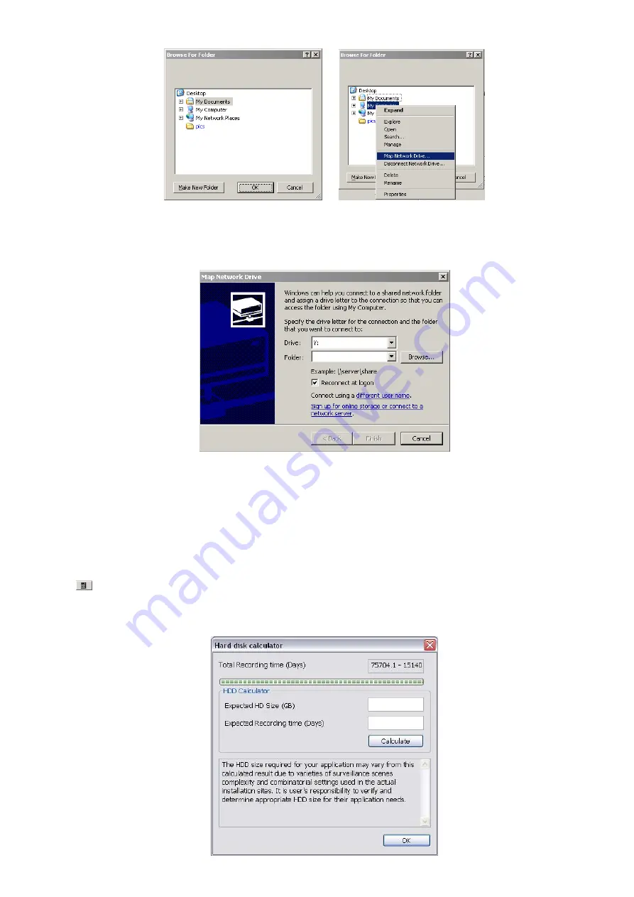
In the 

Map Network Drive

 windows, select the 

Drive

 and fill in the network drive direction in 

Folder

 column 

if you know. Or click 

Browse

 to find the folder direction. Click 

Finish

 to complete the network drive mapping. 

After the network drive has been added, user needs to create a folder for network storage. In 

Browse For 

Folder

 windows, select the network drive and right click mouse button to add a new folder. And then, click 

OK

. User should see a new storage folder display in Storage path list. 


By default the data is stored in C:\Data, to insert another storage path, click 

Add

. To remove the selected 

path, click 

Delete

. If you want the system to automatically erase the data after a certain days, enable the 

Delete recorded data after

 check box and enter the numbers of days in 

Days

 text box. If you want the 

system to automatically erase the event and alarm log after a certain days, enable the 

Delete event and 

alarm log after

 check box and enter the numbers of days in 

Days

 text box. To change logs save direction, 

enable 

Move to

 and select the new save direction. 

(2) Hard Disk Calculator 

Estimate the hard disk recording capacity. The result of calculation is a rough value which only for reference. 

The hard disk record capacity will be varied by the real record quality and complexity of video scene.   

Click 

,  the  hard  disk  calculator  windows  will  show  up. 

Total  Recording  time

  is  the  current  hard  disk 

recording  capacity.  Enter  the  expect  hard  disk  size  or  expect  recording  time  in 

Expected  HD  Size

  or


Expected Record time

, and then click 

Calculate

 button. Click OK to exit the hard disk calculator windows. 

The hard disk calculation will base on the recording setup and current hard disk setup.


Summary of Contents for IWH3216 Touch

Page 1: ...AVerMedia IWH3216 Touch User Manual June 2010...

Page 2: ...s relating to Electromagnetic Compatibility Directive 2004 108 EC Warning This is a Class A product In a domestic environment this product may cause radio interference in which case the user may be re...

Page 3: ...CAUSE INSTABILITY OF THE SYSTEM CAUTION IF THERE IS ANY DAMAGE SHORTAGE OR INAPPROPRIATE ITEM IN THE PACKAGE PLEASE CONTACT WITH YOUR LOCAL DEALER WARRANTY VOID FOR ANY UNAUTHORIZED PRODUCT MODIFICATI...

Page 4: ...3 3 1 To Cut and Save the Wanted Portion of the Recorded Video 23 3 3 2 To Bookmark a Section of the Video 24 3 3 3 To Search Using the Visual Search 25 3 3 4 To Search Using the Event Search 26 3 3...

Page 5: ...97 4 9 11 Missing Suspicious Object and Scene Change Detected 98 4 10 User Setting 100 Chapter 5 Backup Video Players 102 5 1 Familiarizing the Buttons in QPlayer 102 Chapter 6 Using the Remote Progra...

Page 6: ...ble 146 Chapter 8 Web Tools 148 8 1 Dispatch Server 148 8 2 Remote Setup 149 8 2 1 To Add DVR server 149 8 2 2 To Setup Remote DVR Server 150 8 2 2 1 System Setting 150 8 2 2 2 Camera Setting 153 8 2...

Page 7: ...ion Power Cord The power cord may vary according to the local electricity system Power Adaptor Audio in cable 2 Spot monitor cables are included Video in cable 16channels i If there is any damage shor...

Page 8: ...line out signal Microphone Input 1 ch line in signal Alarm Inputs 16 Input voltage max 6 VDC Relay Outputs 4 PTZ control analog Protocol supported Pelco D Pelco P DynaColor Lilin PIH7622 CD55 DiGiDome...

Page 9: ...Central Management CM3000 CM3000 Gold Central Management System to support up to 1000 DVRs Remote Access Webcam via regular IE browser Remote Console SmartViewer PDAViewer JAVAViewer iPhoneViewer Dis...

Page 10: ...setup window To move PTZ camera lens to left right up and down in PTZ mode Touch the blue area to go to next or previous frame Go forward direction is Next frame and backward direction is Previous fra...

Page 11: ...13 Number buttons Channel camera selection number in playback and preview mode For the channel over 10 press then press Press button can switch to different screen display modes Press and number butto...

Page 12: ...sary 4 Relay Out Support 4 relay devices Relay 1A 125V AC 30V DC 5 Sensor In Support up to 16 sensor devices 6 MIC In To connect the microphone 7 USB port For connecting USB interface devices such pen...

Page 13: ...s of hard disk plate 4 The hard disk plate can be installed 3 hard disks User can choose the position and place the hard disk on it 5 Turn the plate and hard disk over carefully and secure the hard di...

Page 14: ...8 7 Plug the power cables and SATA cables into all three hard disk 8 Screw the holder 9 Push the cover forward and secure the cover 10 User may now connect all the cables and power on the DVR unit...

Page 15: ...nit also can connect 16 sensor devices 4 alarm devices and output video to 2 CRT LCD monitor Follow the illustration below to make the connection For backup recorded video plugging the pen drive or ex...

Page 16: ...and this triggers the system to respond and send signal to relay device i e alarm telephone etc Pin Definition Pin Definition 1 Relay Signal 1 14 Sensor Signal 7 2 Relay Signal 2 15 Sensor Signal 8 3...

Page 17: ...fter enter the CD Key the DVR will enter preview mode of DVR application The following chapter will describe the functions of Preview Playback and Compact mode of DVR application 3 2 Familiarizing the...

Page 18: ...amera and Drag on where you want to relocate it To only display one of the video in the multiple screen mode Left click on the video screen you only want to display 3 Status Bar It shows the current t...

Page 19: ...low If you assign a split display mode and appoint a camera number the icon group of the cameras will turn yellow altogether 13 iPOSLive To view the real time iPOS data of channels Click the iPOSLive...

Page 20: ...ll screen in multiple screen mode Left click to toggle to only display one of the video in the multiple screen mode or all 18 Alarm Click Alarm Status button to view the status or advanced alarm infor...

Page 21: ...ertain event log by key word Enter the key word in Find Text column and click Search button 3 To filter the records select and click the select button to display Event System Operation Network or All...

Page 22: ...exactly box if wants to find exactly key word or word string of POS event log 5 Export POSDB It allows user to save the POS database to selected storage path in excel format Click to change the stora...

Page 23: ...2 1 1 Select the Date and set a time period between After and Before for object counts searching 2 Select the search Event In Out or All 3 Select one Camera or All cameras to search 4 Click Search to...

Page 24: ...Viewer window 2 Search Mode Switch to face object log search mode In search mode UI select the Time and Camera to search the object log The result will display at Object Log window 3 Select Camera Se...

Page 25: ...e track 3 Hour Buttons Select and click to playback the recorded video file on the specific time frame i The Hour buttons represent the time in 24 hour clock The blue bar on top of the hour button ind...

Page 26: ...from 00 to 23 represent the time in 24 hour clock The numbers from 01 to 16 represent the camera ID The blue colored column indicates that there is a recorded video file on that period of time While t...

Page 27: ...o view and the iPOS detail will display in Search Receipt To save the search result click Save button Click Print button to print the search result To save the selected iPOS search receipt click Save...

Page 28: ...urn for later reference You may also set it to protect the file See also Chapter 3 3 2 16 Visual Search Search from a specific camera by Date Hour Minute 10 Seconds and Second See also Chapter 3 3 3 1...

Page 29: ...click Segment button again 3 Click Export button Output Video Clip button to save the wanted clip 4 In the Save As dialog box locate on where you want to save the file or choose to Burn the video segm...

Page 30: ...rotect to prevent the bookmark file to be deleted i When the bookmark is protected the file won t be overwritten The protect file can be deleted only when the Delete the recorded data is enable in the...

Page 31: ...r and the date Then click OK 3 When a series of frames appear by date click on the frame to display another series of frames and search by every Hour of that date every Minute of that hour every 10 Se...

Page 32: ...Text box type the word Then click OK to start searching The video search would stop at the frame that matches the condition To keep on searching click Find Next button 4 You may also set to search an...

Page 33: ...nd the motion detector frame size and location To set motion detector frame size and location left click and drag on the screen Then click OK to start searching The video search would stop at the fram...

Page 34: ...lit screen mode When you are in single screen mode Right click and Drag a square on the area you want to enlarge When you are in multiple screen mode Right click the video screen of the camera and Dra...

Page 35: ...Focus Adjust the focus manually to produce clear image 5 Zoom Zoom in and out the image 6 Direction buttons Adjust and position the focal point of the PTZ camera 7 Camera ID pane Display the PTZ came...

Page 36: ...ap screen click Edit You may now drag the camera sensor and relay icons to its place on the map Icons on the map can be relocated anywhere 5 To set the camera direction right click camera icon can sel...

Page 37: ...located on the map and to display the video at the upper right corner of the Emap screen At the lower right corner of the Emap screen it lists all the warning message 3 To control relay right click r...

Page 38: ...to keep the settings 6 Repeat step 4 5 if you want to save another PTZ camera position 7 Restore AutoPan Time set a time period for restoring auto path function after the PTZ camera has been moved Mar...

Page 39: ...r will show up on the screen i User can move the on screen PTZ controller to any position of screen The on screen PTZ controller only display on a channel screen at a time 16 Using the red cross mouse...

Page 40: ...e box and in the Preset Name text box type the word When done click Save to keep the settings 7 Repeat step 5 6 if you want to save another IP PTZ camera position 8 Restore AutoPan Time set a time per...

Page 41: ...r will show up on the screen i User can move the on screen PTZ controller to any position of screen The on screen PTZ controller only display on a channel screen at a time 17 Using the red cross mouse...

Page 42: ...o save the data When there is not enough free space to record one hour data the system automatically replaces the oldest data In case you have more than one storage path the system automatically saves...

Page 43: ...and enter the numbers of days in Days text box If you want the system to automatically erase the event and alarm log after a certain days enable the Delete event and alarm log after check box and ente...

Page 44: ...appear on TV spot monitor and set the Autoscan time gap from 3 to 10 sec before it switches to the next camera 7 Configuration Backup a copy of all the settings and allows you to regain the same setti...

Page 45: ...he video from the last hour Instant Playback Automatically playback the video which has just recorded To set the instant playback time period fill in the time in second at Set Instant Playback s Play...

Page 46: ...lick OK to save the configuration Display Setting Adjust resolution of display and adjust the touch monitor Click Advance Setup to configure the monitor detail setting and the detail setting of monito...

Page 47: ...lected hard disk into Partition Table section 3 User can adjust the capacity of partition by clicking Capacity column and enter the capacity If user doesn t want to divide hard disk into several parti...

Page 48: ...he DVR to 1 0 0 0 network segment It will cause the DVR cannot access to Internet due to the un recognize to 1 0 0 0 IP segment Mask It is a bitmask used to identify the sub network and how many bits...

Page 49: ...lder of file server or NAS on your network in Folder 2 And then click Finish to make the connection 3 After connection successful user should see the network drive on the Storage Path 4 To disconnect...

Page 50: ...nter and following the wizard to install a printer Regional Language Setting When DVR application is using different language of UI besides English user can select the corresponding region and languag...

Page 51: ...45 Power Management To setup UPS configuration Device Management To manage the DVR system devices...

Page 52: ...46 Network Connection To manage the connection of the network Phone and Modem options To setup the modem dial up settings Usageinfo To view usage of the system CPU memory and network...

Page 53: ...f the System Controller If System Controller is connecting to DVR through the USB port please select the System Controller Pro mode If System Controller is connecting to DVR through the RS485 port ple...

Page 54: ...ting Click OK to save and close POS Console Setting 3 In the POS Mapping dialog box click OK to accept the settings and Cancel to exit without saving the new setting 1 2 3 5 7 8 4 6 1 Name Enter a nam...

Page 55: ...UDP protocol for remote connection if POS system can broadcast to Internet Enter the IP address of the remote station 6 Setup Set the COM Properties If you are not sure please contact your POS servic...

Page 56: ...save 5 To modify existing device double click it 6 Click Default can be reset back to original setting Add Rules 1 Select the POS device form device list 2 Click Add in Rules section 3 In Rule Settin...

Page 57: ...ment Set a rule to replace a character or word in POS data The maximum replacement is 8 1 Select a POS device from device list 2 Click Add in Replace section 3 Old Data select the Type Ascii or Hex an...

Page 58: ...in here Click Add to add a device Enter device name and select Type as XML The POS device can be added up to 50 include defaults Page Start Beginning of data for transaction Page End End of data for...

Page 59: ...g MessageVersion 1 0 MessageVersion Date 20060317 Date Time 164216 Time RegisterID 3 RegisterID Sub tag Shift 4 Shift CashierID 000000009 CashierID JrnlTransNum 3 JrnlTransNum JrnlID 0 JrnlID Header T...

Page 60: ...llance screen Left Top Left Bottom Right Top or Right Bottom 5 Mark Multiple Windows to allow more than one iPOS live data window see also 13 iPOS Live in Preview mode display on the preview screen mo...

Page 61: ...tion or storage device Click to change the save path Mark Remove POS data after the POS data will be delete from DVR hard disk on the day that user has setup Also mark Move to user can save the POS da...

Page 62: ...con The camera icon turns red when it is selected The camera icon will be different that depends on the camera type user selected IP camera icon Analog camera icon 2 Enable Set to enable disable the s...

Page 63: ...vailable enter the IP address at IP Camera Site column Or User can click Search Device to find the selected protocol of camera on the LAN network If user is not sure the camera is which model click De...

Page 64: ...Enable update when motion The video will update only when compare the key frame has motion found and then the video will be displayed Schedule Connect User can select a certain date and time to conne...

Page 65: ...n enter relay description 4 In the test section click Test to trigger relay Red is high and Green is low 5 Click OK to exit and accept the setting and Cancel to exit without saving the setting Direct...

Page 66: ...ounting Select the two regions on the screen and the system will count the objects that appear from one selected region to another selected region See also Chapter 4 2 1 i The DVR system only supports...

Page 67: ...define the detected object dimensions Press left button of mouse and drag on the screen To see the object size frame on screen enable Moving Object in Display section 5 Adjust the sensitive of object...

Page 68: ...ve the setting Click Cancel to leave the setup window without saving 9 The object counting information will be display on the screen of upper part Object Counting Information Display Region 1 Region 2...

Page 69: ...p window User can select multiple areas for detection To clear the selected area right click the mouse button and drag the selected area to clear Or click Clear to clear all selected areas Detection S...

Page 70: ...normal status It works only when the activate status is set to trigger After set up click Start Test to test the configure result When the system is detecting face the red frame will show up on the s...

Page 71: ...s to complete the PTZ tracking 1 Show Trigger Line in Live Video Enable disable the tracking line on the preview screen 2 Left Trigger Line red line Set the left edge of the tracking range If the obje...

Page 72: ...e sure the PTZ tracking will be restored after manually control of the PTZ camera 7 Go to PTZ Preset Position To move the PTZ camera back to the selected preset position after PTZ camera tracking the...

Page 73: ...camera group The maximum of group number is 64 The default group can be deleted and modified 1 Click to add a new group 2 Right click on group to rename the group name 3 Drag the camera from Camera l...

Page 74: ...with camera 9 In camera group different camera icon represent different types of camera IP camera Analog camera and Camera of remote DVR 10 User can easy to view and manage the camera group in preview...

Page 75: ...ect one camera only Left click on the camera icon The camera icon turns red when it is selected The camera icon will be different that depends on the camera type IP camera icon Analog camera icon 2 Re...

Page 76: ...ce Detecting Recording DVR system will record the sound when the voice exceeds the intensity value in Voice Detection setting No Recording The system won t do any recording KeyFrame Recording Only rec...

Page 77: ...pturing motionless picture and 2 if it captures lots of movement 9 Mask Shield Edit Mask mark an area on the screen to disregards the motion in the marked area and to only monitor outside the marked a...

Page 78: ...ault Mode High Medium Low Click button to view default mode definition 12 Group Click to view the camera group that user has been setup in Camera setup see also Chapter 4 2 4 13 Camera Click to view t...

Page 79: ...a only Left click on the camera icon The camera icon turns red when it is selected The camera icon will be different that depends on the camera type IP camera icon Analog camera icon 2 Recording Mode...

Page 80: ...Voice Detection setting No Recording The system won t do any recording KeyFrame Recording Only record one frame per second 3 Motion Detection Adjust the sensitivity of the motion detector The higher...

Page 81: ...camera 4 3 3 To Mask Shield an area on the screen 1 In the Mask Shield Edit section activate the Enable Mask Enable Shield check box 2 Enable the Show Mask check box to show the mask frame on surveil...

Page 82: ...y number product name password and user information Use this service if the IP address changes each time when you connect to internet 5 Remote Control Server Enable disable remote control from remote...

Page 83: ...ss or domain name Select Automatic Synchronize time to set automatic synchronize time on a daily basis Or user can click Synchronize Time Right Now to adjust time right away 10 3GPP Enable 3GPP that a...

Page 84: ...78 Network Bandwidth Limit By Channel Set the network bandwidth by each channel All Set the total network bandwidth consumption limit...

Page 85: ...set time and specified backup path DVR automatically updates and only backup the data that are not yet included in the archive To assign backup path click Mirror Backup Save a copy of all the data at...

Page 86: ...ekly or one time Click to make a selection 4 Click on the blocks Right click the colored blocks to set the schedule In the Select time dialog box click to enable or disable the portion user want to se...

Page 87: ...p file 1 Select the date of the recorded file in the calendar you want to backup Use and buttons to shift the calendar to the left or right 2 In the table below click on the blue block to select the r...

Page 88: ...ist shows the archived item Select the item in the list and click Burn Click Exit to end this procedure and burn it later 9 In CD DVD Backup enable disable Delete file after burning check box to remov...

Page 89: ...to configure external I O device if it is available see also Chapter 4 7 1 4 The system automatically detects the sensor and input relates information User can enter a short description for this relay...

Page 90: ...t parameters Please refer to the external I O box s user manual for port setting information Using the default value if user uses External I O box 5 Click OK to save the setting 6 To add more than one...

Page 91: ...O device if it is available see also Chapter 4 7 1 When external I O is set and it will be available in drag down list for selecting 4 The system automatically detects the card and input number User c...

Page 92: ...and description 3 In 2 Enable Time the number from 00 to 23 represent the time in 24 hour clock Click Schedule to select the time and date that you want to activate or deactivate the alarm function Se...

Page 93: ...also Chapter 4 9 11 In Audio Detect click the camera number to the system to alarm when detect the abnormal audio 5 In 4 Sensor select and click on the sensor number to set the condition for the syste...

Page 94: ...limited of system for system to alarm When DVR system temperature is over the temperature limited the system will send out the alarm Illegal Entry any objects move between selected regions which user...

Page 95: ...and select the alarm button and fill in the description of alarm button When the alarm buttons have been setup the Alarm Button icon will show up on the DVR application UI User can click the Alarm but...

Page 96: ...V automatically If the retrieve time is un mark the alarm video will keep displaying until user switch back to normal display mode manually The retrieve time range is 3 600 seconds Enlarge Camera View...

Page 97: ...cation protocol WAP Make sure your mobile phone support this feature and your PC is connected to GSM GPRS modem To setup click Detail see also Chapter 4 9 6 PTZ preset point Position the PTZ camera ba...

Page 98: ...mit on hard disk When the snapshot images storage limit has reached the DVR system will delete the snapshot images from hard disk 4 9 1 To Setup Alarm Relay 1 Next to the Relay Output check box click...

Page 99: ...el to record stop play rewind and forward If you want to keep the existing file click File Save As enter filename and click Save Make sure you have microphone connected to your PC 5 Click OK to exit a...

Page 100: ...dress with the alarm message 4 Modem Dial up Setting If you are using dial up modem enable Auto Dial up check box and select the modem name You may also set the time to disconnect automatically just e...

Page 101: ...s based on the available speed 4 In the Stop Recording after text box set the number in second for the program to continue recording after the alarm has ended 5 Click OK to accept the new settings and...

Page 102: ...at transmitting RS232 port can t be connected to SMS MMS modem you need to use USB to RS232 converter to connect 4 9 7 To Setup PTZ Preset Point Next to the PTZ preset point check box click Detail In...

Page 103: ...rd Setting select the camera to enable disable scanning the keyword Enable All to select all cameras 3 Enter the text below keyword text box Click Add to include the keyword in the list To remove sele...

Page 104: ...g the object missing or the doubtful object appears on the screen Click OK to save and exit the setup windows To exam the setup condition click Start Test 1 Select the camera number 0 16 and press rig...

Page 105: ...ay on screen The reference image is sharing with the Missing Object and Suspicious Object function 3 Mark the Enable check box to setup the condition 4 Sensitive Set the system detects sensitivity 5 D...

Page 106: ...lect the status of the user Only Administrator level can access User Setting and reset the Alarm status when using the Remote Console 2 Control Right Enable the items that would allow the user to acce...

Page 107: ...hat would allow the user to access or view To select all the cameras enable the ALL check box 5 Time Span Set the user account a specific time period that user only can use given account to login DVR...

Page 108: ...om in an area on the screen Right click and Drag a square on the area you want to enlarge 2 Exit Close the player 3 Progress bar Show the progress of the file being played You may move the bar to seek...

Page 109: ...the recorded video file 7 Status bar Display the recorded date time and play speed 8 Camera ID Show the number of cameras that are being viewed When you are in single screen mode click the camera ID...

Page 110: ...xt event or changes in the motion detector frame You can use this when you are using Intelligent Search or Event Search function 16 Event Search Search from the recorded activities that take place in...

Page 111: ...er to install WebCamX cab allow the installation and you should be able to connect and login afterwards Click Install when the Internet Explorer Security Warning dialog box appears After installing th...

Page 112: ...via internet using MIC Make sure your microphone and speakers work before using this function If the DVR server Talk to web client setting is disabled you won t be able to hear from the other side 7...

Page 113: ...rmal or Low Click Add Server and select the server type between DVR and IP Cam to add Click Delete Server to delete the selected item Click Import to replace it with the previous saved list Click Expo...

Page 114: ...ct the camera you want to adjust the settings 2 Enable Set to enable disable the selected camera When there is no video source on the camera we suggest disabling it so that the system won t detect it...

Page 115: ...Deinterlace mode to 1 if you are capturing motionless picture and 2 if it captures lots of movement Enable Audio Select to assign the audio channel of the selected camera You can only assign one audi...

Page 116: ...nu bar will appear as below shown Click the setup selection to enter the setup window To exit setup menu bar click OK System Setting In the System Setting windows click Update to accept the new settin...

Page 117: ...om 3 to 10 sec before it switches to the next camera 6 Login Enable the conditions in Login section you want the system to automatically carry out Auto record when login Automatically start video reco...

Page 118: ...ced 1 Mark Show POS Text to allow POS data to be display on surveillance screen 2 Select the POS data display position on surveillance screen Left Top Left Bottom Right Top or Right Bottom 3 To change...

Page 119: ...selected camera When there is no video source on the camera we suggest disabling it so that the system won t detect it as video loss error 3 Camera Display Enable disable to show the video Even if the...

Page 120: ...To select all the cameras enable the ALL check box To select more than one camera Right click on the camera icon To select one camera only Left click on the camera icon The camera icon turns red when...

Page 121: ...lect the recording mode and click the button If you want to only record at a particular time click the Schedule button and click colored block then click on the time blocks in Recording Mode window Wh...

Page 122: ...ssion level and uses more hard disk space 6 Frame Rate Set the maximum number of frames to be recorded during motion and motionless state The frame rate ranges from 1 to 30 for NTSC and 1 to 25 for PA...

Page 123: ...g Start recording the video from the selected camera only when the system detects movement Once a motion is detected the system automatically saves the previous frames and stop based on the Start Reco...

Page 124: ...Server Enable disable remote control from remote application ex CMS Enter the remote accessing port in Port column 5 Network Video Configuration Set up the video quality and frame rate for viewing an...

Page 125: ...with old remote software Enable White List An access permit list for the remote accessing of DVR server Enter the IP address and click Add Or enter a range of IP address and click Add To delete the IP...

Page 126: ...ta at the set time and specified backup path DVR automatically updates and only backup the data that are not yet included in the archive Mirror Backup Save a copy of all the data at the set time and s...

Page 127: ...set the schedule In the Select time dialog box click to enable or disable the portion user want to set Click OK to accept the setting and Cancel to exit without saving the setting 5 User also can clic...

Page 128: ...from 00 to 23 represent the time in 24 hour clock Select the time and click the block you want to enable or disable the alarm function When it is disable the color of the block turns white 4 In 3 Con...

Page 129: ...ndition the system will send out the alarm message Abnormal Reboot when the DVR system reboot in irregular condition the system will send out the alarm message Recording is switched off when the recor...

Page 130: ...et the alarm action for the system to perform when the alarm condition is activated Launch E Map Display mini Emap screen TV Out Switch to only display the video on TV from where the alarm is activate...

Page 131: ...alog box click OK to exit and save the setting and Cancel to exit without saving the setting 1 SMTP Server Enter the SMTP Server and port If your e mail system requires user identification enable Auth...

Page 132: ...Frame Rate selection select As Setting to record the number of frames based on the Recording Setting or Max to record the maximum of frames based on the available speed 4 In the Stop Recording after t...

Page 133: ...he PTZ camera In the Select PTZ dialog box Select column click to enable disable viewing and controlling the PTZ camera Click OK to exit and save the setting and Cancel to exit without saving the sett...

Page 134: ...access DVR server from a remote location via internet connection 8 Setup Configure the Remote Console setting see also Chapter 6 3 1 9 PTZ Access PTZ control panel Beside PTZ camera DVR system also s...

Page 135: ...system automatically saves the data to the next storage path By default the data is stored in C RemoteData to insert another storage path click Add To remove the selected path click Delete If you want...

Page 136: ...ion number 4 Focus Adjust the focus manually to produce clear image 5 Zoom Zoom in and out the image 6 Direction buttons Adjust and position the focal point of the PTZ camera 7 Camera ID pane Display...

Page 137: ...r To switch to channel group click Channel 01 16 and Channel 17 32 button but if DVR supports less than 16 channels include 16 channels and the channel group switching buttons are non functional To Ma...

Page 138: ...click to playback the recorded video file on the specific time frame i The Hour buttons represent the time in 24 hour clock The blue bar on top of the hour button indicates that there is a recorded v...

Page 139: ...to switch and view other camera 11 Export Export includes Snapshot Print Output Video Clip and Backup function Snapshot Capture and save the screen shot either in jpg or bmp format Print Print the sc...

Page 140: ...Visual and Intelligent search only available when the remote site is recording and playback from remote local hard disk 19 Audio Enable disable audio play 20 De interlace To enhance the video quality...

Page 141: ...i The Hour buttons represent the time in 24 hour clock The blue bar on top of the hour button indicates that there is a recorded video file on that period of time While the red bar indicates that you...

Page 142: ...recorded date time and play speed 10 Camera ID Show the number of cameras that are being viewed When you are in single screen mode click the camera ID number to switch and view other camera 11 Export...

Page 143: ...r 32x Next Go to the next frame End Go to the end of the recorded video file 4 Status bar Display the recorded date time and play speed 5 Language Select the language of function tips 6 Export Export...

Page 144: ...earch or Event Search function 12 Event Search Search from the recorded activities that take place in the system i e Sensor Motion Video Loss POS See also Chapter 3 10 13 Intelligent Search Search the...

Page 145: ...R through Internet Make sure your PDA support IE browser and is connected to the internet To use this feature you need to install the PDAViewer software either thru ActiveSync connection or download i...

Page 146: ...ted to the internet 2 Open the web browser and enter the server IP Then click the hyperlink Download PDA Viewer 3 When the Download dialog box appears enable Open file after download and click Yes 4 A...

Page 147: ...on type Then click OK User can playback the recorded video from remote DVR server in PDAViewer see Chapter 6 6 4 2 Split Screen Mode Select between 2 screen display types It also allows you to switch...

Page 148: ...pup menu will appear 6 6 4 To Playback in PDAViewer 1 Run the PDAViewer in the Programs 2 Hook up to the DVR server 3 Click Connect icon and select the DVR server 4 Click Playback to enter playback op...

Page 149: ...OS and can be connected to the internet To use this feature you need to install the JAVAViewer program that it can be downloading it from the DVR server through the internet To install JAVAViewer fro...

Page 150: ...elect the Connect to connect to DVR server 4 Click Yes to accept the data from DVR server 5 When connection is success you will see the camera video on the screen 6 To switch to different camera view...

Page 151: ...vi format 5 Print Print the screen shot 6 Segment Mark the beginning and the end of the wanted portion of the video Two triangle marks will appear on the slider To cancel video segmentation click this...

Page 152: ...and select the recorded video 2 And then click iStable button 3 iStable windows will show up 4 Select the smoothness level 1 Low 2 3 4 and 5 High The default value is 3 5 Click Play button and then i...

Page 153: ...147 10 To switch back to iEnhance interface click iEnhance button...

Page 154: ...R Web Tool iDispatch Server 3 In the DVR Server section enter the DVR server IP port user ID and password You can also select to display the language you prefer 4 Auto connect when start Enable to aut...

Page 155: ...port number is same the WebViewer port on the remote DVR server The default is 80 User ID fill in the remote DVR server s login account Password fill in the remote DVR server s login password Descript...

Page 156: ...nd select the proper video system according to your camera video system If the video system setting is wrong the video would appear abnormal 4 Attention Please Check the attentiveness of the person wh...

Page 157: ...ack Mode Select the mode of playback the video Select date and time Select the date and time which user wants to playback Play the last file Automatically playback the video from the last hour Instant...

Page 158: ...To select all channels mark All check box 9 UPS Uninterruptible Power Supply Protect the system from damaging such as power surges or brownouts This automatically gives time to close the DVR properly...

Page 159: ...the selected camera When there is no video source on the camera we suggest disabling it so that the system won t detect it as video loss error 3 Camera Display Enable disable to show the video Even if...

Page 160: ...To select all the cameras enable the ALL check box To select more than one camera Right click on the camera icon To select one camera only Left click on the camera icon The camera icon turns red when...

Page 161: ...s select the recording mode and click the button If you want to only record at a particular time click the Schedule button and click colored block then click on the time blocks in Recording Mode windo...

Page 162: ...ssion level and uses more hard disk space 6 Frame Rate Set the maximum number of frames to be recorded during motion and motionless state The frame rate ranges from 1 to 30 for NTSC and 1 to 25 for PA...

Page 163: ...ignated storage path Motion Recording Start recording the video from the selected camera only when the system detects movement Once a motion is detected the system automatically saves the previous fra...

Page 164: ...trol Server Enable disable remote control from remote application ex CMS Enter the remote accessing port in Port column 5 Network Video Configuration Set up the video quality and frame rate for viewin...

Page 165: ...with old remote software Enable White List An access permit list for the remote accessing of DVR server Enter the IP address and click Add Or enter a range of IP address and click Add To delete the IP...

Page 166: ...e data at the set time and specified backup path DVR automatically updates and only backup the data that are not yet included in the archive Mirror Backup Save a copy of all the data at the set time a...

Page 167: ...set the schedule In the Select time dialog box click to enable or disable the portion user want to set Click OK to accept the setting and Cancel to exit without saving the setting 5 User also can clic...

Page 168: ...mber from 00 to 23 represent the time in 24 hour clock Select the time and click the block you want to enable or disable the alarm function When it is disable the color of the block turns white 4 In 3...

Page 169: ...to scan the data from the POS if it matches the keyword see also Chapter 4 9 10 Alarm Message To active with external alarm message by your own program For the detail configuration please contact the...

Page 170: ...To Setup Send E mail File Transmission via FTP Upload file to remote computer thru FTP File Transfer Protocol To setup click Detail see also To Setup FTP Start Recording Record the video from the sel...

Page 171: ...Select the image size and set the number of frames Attach image when sensor is triggered When the sensor is triggered the system will capture the image and send the image to the certain e mail addres...

Page 172: ...after the alarm has ended 10 Click OK to accept the new settings and Cancel to exit without saving To Setup Alarm SOP Next to the Alarm SOP check box click Detail In the step text boxes type the stand...

Page 173: ...te i To back up the data you must have at least 2G hard disk space To back up the recoded data from the DVR server 1 Make sure you are connected to the internet 2 Click Start Programs DVR Web Tool Rem...

Page 174: ...le Manual Backup mode the backup progress will start when user press the backup button Click File Select to choose the date time and camera you want to back up Click Browse to set the storage path 6 C...

Page 175: ...169 8 For manually backup click file select button 9 And then select the date and time that user wants to backup 10 In Remote Backup window click Start button to backup...

Page 176: ...170 11 If user wants to burn the back file into DVD disk click Burn button and select the file to burn...

Page 177: ...Browse the website ddns avers com tw with Microsoft IE to access the following dialog First input CD Key number that is located at back panel of the DVR server and select the product name Then click O...

Page 178: ...he following table shows the ports that DVR server uses for certain network service Port Variable Remote Console CM 3000 5550 Y WebCam 80 Y 2 way audio 9999 Y Remote Control CM3000 5555 Y DVR POS 5150...

Page 179: ...ow the below steps to setup the RAID 1 Restart the DVR system and press Delete button to enter the BIOS setup screen 2 Select the IDE Configuration and press Enter button 3 In Configuration SATA 1 as...

Page 180: ...174 4 When the below screen show up press CTRL I 5 Select Create RAID Volume...

Page 181: ...175 6 In Create RAID Volume Menu screen select RAID Level that user wants to create Using up and down button to change selection...

Page 182: ...ss Enter to the select disks screen Using Space key to select the disk The selected disk will have a green triangle mark 8 After select the RAID level and disks press Enter key to create the RAID volu...

Page 183: ...lume created user should see the RAID volume information in DISK VOLUME INFORMATION section 10 The RAID volume needs to be formatted before using Please refer to Disk Management of 13 System Configura...

Page 184: ...ress Esc key press CTRL I 2 Select Delete RAID Volume 3 Select the RAID volume if there is more than one RAID volume Press Delete key and press Y to delete the RAID volume Note It is not available to...

Page 185: ...that this product will meet your requirements it is your responsibility to determine the suitability of this product for your purpose WHAT WE WILL AND WILL NOT PAY FOR We will pay labor and material...

Reviews: