


MDF/lDF DESIGN: DEFINITY GENERIC 2 WITH UNIVERSAL MODULES
7-5
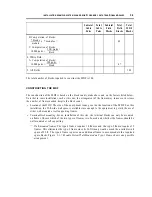
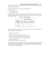
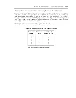
RECOMMENDED FRAMES
FOR TERMINAL BLOCKS
The extra-large building entrance terminal (XLBET) frame, which is manufactured at the AT&T Los
Angeles Service Center, can be used for the MDF. The frame comes in single- and double-sided
versions that are 84 in. high, 10 in, deep (single-sided) to front edge of wireway with rear foot removed,
20 in. deep (wireway-to-wireway), and 24 in. wide. (All frame illustrations shown in this document are
the standard 84-in. high frame. You may use taller frames in special circumstances as explained below
in Customization,)
Several characteristics make the AT&T frames preferable when installing a Generic 2 with universal
modules. They are:
●
Frontal connectorization. AT&T frames have specially designed connector panels located at the
front and top.
NOTE:
Connector mating on any type of trough or ladder rack is prohibited.
●
Color selection. AT&T frames are manufactured in the same colors as AT&T equipment cabinets.
The color match of the frames and cabinets considerably enhances the appearance of an installation.
●
Ordering simplicity. AT&T frames are easy to order: you submit one comcode to obtain the frame
and the terminal blocks, which come assembled as a complete unit. You only order ladder racks and
insert labels separately.
●
Customization. You can order AT&T frames in special heights to accommodate connector panels,
equipment rooms with high ceilings, or equipment rooms with raised floors. Also, you can
order frames fitted with mountings for protector units.
Whenever possible, use the XLBET frames, either self-supported or wall-mounted, for the MDF. The
benefits and advantages, for both the customer and AT&T, of easier ordering, better aesthetics, and
easier connecting and disconnecting of jumper wires more than offset the slightly higher cost over wall
modules. For systems larger than five modules, try to design the MDF with self-supported frames.
Self-supported frames allow the most flexibility for handling jumper wires and permit the most efficient
cable terminations. But whether the frame is wall mounted or self supported, attempt to use one of the
two types of XLBET frames discussed below.
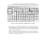
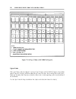
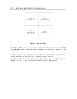
Type-1
Frame
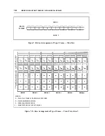
The type-1 frame shown in figure 7-3, Six Type-1 Frames with 18,000-Pair Capacity, is the most widely
used. You can terminate 3000 cable pairs on each side. Cross-connections on the type-1 are made
between the top and the bottom of the frame. This means that all equipment cables are connected to the
top half of the frame and all distribution cables to the bottom half. Exceptions occur only at the green
(CO) and yellow (miscellaneous) fields.
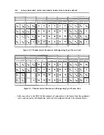
The type-1 frame is most suited for lineups not exceeding nine frames, although it can be used for larger
lineups if necessary. (A discussion of its use in large lineups appears under Designing the MDF later in
this chapter.)
Summary of Contents for 9601
Page 1: ...555 104 630 Issue 2 June 1991 DEFINITY Communications SystemGeneric 2 and System 85 Wiring ...
Page 57: ...2 34 MDF IDF DESIGN SYSTEM 85 AND DEFINITY GENERIC 2 WITH TRADITIONAL MODULES ...
Page 67: ...3 10 ELECTRICAL PROTECTION SYSTEM 85 AND DEFINITY GENERIC 2 WITH TRADITIONAL MODULES ...
Page 73: ...4 6 PORT PACKS DCP REPEATERS SYSTEM 85 AND DEFINITY GENERIC 2 WITH TRADITIONAL MODULES ...
Page 85: ...6 6 OVERVIEW DEFINITY GENERIC 2 WITH UNIVERSAL MODULES ...
Page 119: ...7 34 MDF lDF DESIGN DEFINITY GENERIC 2 WITH UNIVERSAL MODULES ...
Page 123: ...8 4 ELECTRICAL PROTECTION DEFINlTY GENERIC 2 WITH UNIVERSAL MODULES ...
Page 135: ...10 8 INSTALLATION EXAMPLE DEFINITY GENERIC 2 WITH UNIVERSAL MODULES ...
Page 139: ...11 4 BRI DEFINITY GENERIC 2 WITH UNIVERSAL MODULES ...
Page 174: ...GL 12 GLOSSARY ...