


7-4
MDF/lDF DESlGN: DEFINITY GENERIC 2 WITH UNIVERSAL MODULES
Connecting Jumper Wires
To facilitate cross-connections, connect jumper wires as follows:
●
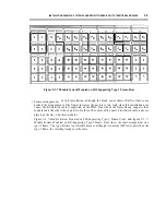
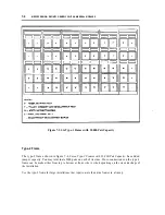
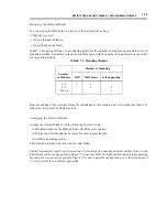
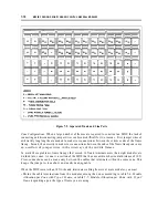
Use the layout and instructions shown in figure 7-2, Jumper Placement, for the 110A terminal
blocks. (Figure 7-2 illustrates a layout for frame mounting, but the layout applies to wall mounting
a s w e l l . )
●
Use only the number of jumpers required for a connection. There is no advantage in using a 3-pair
for a 2-pair circuit.
●
Make sure that 80% of the jumpers are less than 20 ft long. This can be done in the largest of
installations, as described under Designing the MDF earlier in this chapter.
●
Maintain clean contacts on the terminal blocks by using a spudger tool (110 tool; comcode
405423260). Clean contacts by:
— Removing jumpers with a perpendicular motion from the connecting block
— Always using the spudger to clean the contacts immediately after you remove the jumper wires
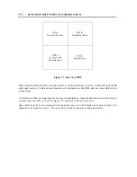
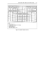
Jumper Placement Rules:
●
Index strips consist of a right and a left half. Dress
pairs l to 12 to the left and dress pairs 13 to 25 to
the right.
●
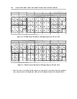
Eliminate "spider webs" and use all horizontal
wireways equally.
●
Use small amounts of diagonal dress in the
horizontal wireway system, if needed, but avoid
diagonal dress during system installation.
Examples:
●
Block B1, row 7, pair 10 to block B8, row 2, pair
2 4 .
B1 left, V1 up, H1 right, V3 down, B8 left.
●
Block B4, row 6, pair 8 to block B10, row 2, pair
12.
B4 left, V2 down, B10 right.
●
Block B3, row 11, pair 16 to block B5, row 1, pair
1 .
B3 right, V2 up, H2 left, V1 down, B5 right.
Figure 7-2. Jumper Placement
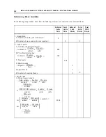
Summary of Contents for 9601
Page 1: ...555 104 630 Issue 2 June 1991 DEFINITY Communications SystemGeneric 2 and System 85 Wiring ...
Page 57: ...2 34 MDF IDF DESIGN SYSTEM 85 AND DEFINITY GENERIC 2 WITH TRADITIONAL MODULES ...
Page 67: ...3 10 ELECTRICAL PROTECTION SYSTEM 85 AND DEFINITY GENERIC 2 WITH TRADITIONAL MODULES ...
Page 73: ...4 6 PORT PACKS DCP REPEATERS SYSTEM 85 AND DEFINITY GENERIC 2 WITH TRADITIONAL MODULES ...
Page 85: ...6 6 OVERVIEW DEFINITY GENERIC 2 WITH UNIVERSAL MODULES ...
Page 119: ...7 34 MDF lDF DESIGN DEFINITY GENERIC 2 WITH UNIVERSAL MODULES ...
Page 123: ...8 4 ELECTRICAL PROTECTION DEFINlTY GENERIC 2 WITH UNIVERSAL MODULES ...
Page 135: ...10 8 INSTALLATION EXAMPLE DEFINITY GENERIC 2 WITH UNIVERSAL MODULES ...
Page 139: ...11 4 BRI DEFINITY GENERIC 2 WITH UNIVERSAL MODULES ...
Page 174: ...GL 12 GLOSSARY ...