


MDF/lDF DESIGN: SYSTEM 85 AND DEFINITY GENERIC 2 WITH TRADITIONAL MODULES
2-17
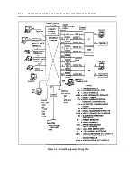
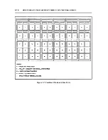
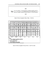
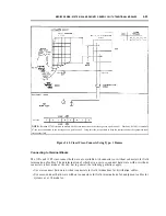
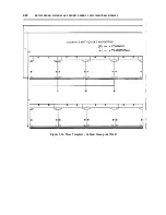
LEGEND:
G — GREEN. NETWORK FIELD
Y — YELLOW, AUXILIARY AND MISCELLANEOUS FIELD
W — WHITE, DISTIBUTION FIELD
PT — PURPLE TRUNK FIELD
PL — PURPLE LINE FIELD
+ — SPARE WITHOUT TERMINAL BLOCKS
S — SPARE WITH TERMINAL BLOCKS
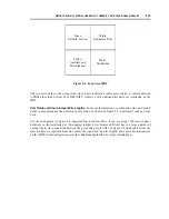
Figure 2-8. Separated Trunk and Line Ports
Zone Configurations.
When a large number of frames are required to construct an MDF, the task of
connecting and disconnecting jumper wires can become difficult for two reasons. First, jumper wires of
awkwardly long lengths are neeed to make cross-connections between the extreme ends of the frame
lineup. Second, the necessity to make cross-connections between the ends of the frame lineup can cause
an overflow of jumper wires in the troughs of the middle frames.
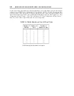
To avoid these problems, divide frame lineups into zones if they exceed 16 ft and terminate more than 5
modules. A zone is a section of the MDF with a maximum horizontal distance of 16 ft. Cross-
connections can be made only between the cables that terminate within the same zone. This keeps the
jumper wires short and easily manageable.
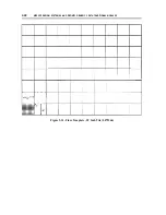
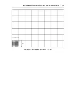
When the MDF is more than 16 ft wide and terminates cabling from 6 or more modules, you must:
●
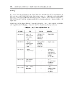
Divide the cable terminations from the modules among the zones according to table 2-5, Module
Allocation per Zone with Type-1 Frame or table 2-6, Module Allocation per Zone with Type-2
Frame, (depending upon the type of frame you are using).
Summary of Contents for 9601
Page 1: ...555 104 630 Issue 2 June 1991 DEFINITY Communications SystemGeneric 2 and System 85 Wiring ...
Page 57: ...2 34 MDF IDF DESIGN SYSTEM 85 AND DEFINITY GENERIC 2 WITH TRADITIONAL MODULES ...
Page 67: ...3 10 ELECTRICAL PROTECTION SYSTEM 85 AND DEFINITY GENERIC 2 WITH TRADITIONAL MODULES ...
Page 73: ...4 6 PORT PACKS DCP REPEATERS SYSTEM 85 AND DEFINITY GENERIC 2 WITH TRADITIONAL MODULES ...
Page 85: ...6 6 OVERVIEW DEFINITY GENERIC 2 WITH UNIVERSAL MODULES ...
Page 119: ...7 34 MDF lDF DESIGN DEFINITY GENERIC 2 WITH UNIVERSAL MODULES ...
Page 123: ...8 4 ELECTRICAL PROTECTION DEFINlTY GENERIC 2 WITH UNIVERSAL MODULES ...
Page 135: ...10 8 INSTALLATION EXAMPLE DEFINITY GENERIC 2 WITH UNIVERSAL MODULES ...
Page 139: ...11 4 BRI DEFINITY GENERIC 2 WITH UNIVERSAL MODULES ...
Page 174: ...GL 12 GLOSSARY ...