


2-14
MDF/lDF DESIGN: SYSTEM 85 AND DEFINITY GENERIC 2 WITH TRADITIONAL MODULES
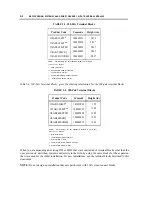
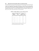
TABLE 2-4. Mounting Methods
Method of Mounting
No. of Modules
Wall
Wall Frame
Self-Supporting
1 - 5
X
X
6 - 1 0
X
X
10 & up
X
Frame mounting of the terminal blocks for installations of all module sizes is desirable, but those of 10
modules or more must be frame mounted.
Arranging the Terminal Blocks
Arrange the terminal blocks with the following factors in mind:
●
Cable terminations to the fields and how the fields cross-connect
●
The type of port fields and the necessity for short jumper lengths
●
Possible zone configurations
These factors are discussed in the sections that follow.
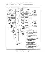
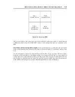
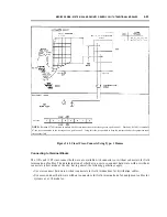
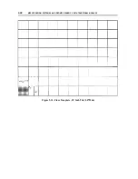
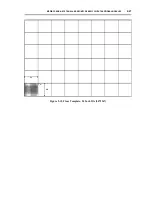
Cable Terminations and Cross-Connections.
Terminate the equipment port cables close to the
distribution cables, as suggested in figure 2-6, Four-Area MDF, to make connecting and disconnecting
the jumper wires as easy as possible; adjust the field design if it is more appropriate for a particular
application.
Summary of Contents for 9601
Page 1: ...555 104 630 Issue 2 June 1991 DEFINITY Communications SystemGeneric 2 and System 85 Wiring ...
Page 57: ...2 34 MDF IDF DESIGN SYSTEM 85 AND DEFINITY GENERIC 2 WITH TRADITIONAL MODULES ...
Page 67: ...3 10 ELECTRICAL PROTECTION SYSTEM 85 AND DEFINITY GENERIC 2 WITH TRADITIONAL MODULES ...
Page 73: ...4 6 PORT PACKS DCP REPEATERS SYSTEM 85 AND DEFINITY GENERIC 2 WITH TRADITIONAL MODULES ...
Page 85: ...6 6 OVERVIEW DEFINITY GENERIC 2 WITH UNIVERSAL MODULES ...
Page 119: ...7 34 MDF lDF DESIGN DEFINITY GENERIC 2 WITH UNIVERSAL MODULES ...
Page 123: ...8 4 ELECTRICAL PROTECTION DEFINlTY GENERIC 2 WITH UNIVERSAL MODULES ...
Page 135: ...10 8 INSTALLATION EXAMPLE DEFINITY GENERIC 2 WITH UNIVERSAL MODULES ...
Page 139: ...11 4 BRI DEFINITY GENERIC 2 WITH UNIVERSAL MODULES ...
Page 174: ...GL 12 GLOSSARY ...