


10-4
lNSTALLATlON EXAMPLE: DEFINITY GENERIC 2 WITH UNIVERSAL MODULES
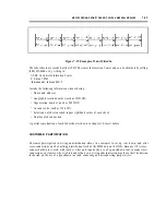
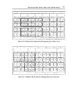
Figure 10-1. 7-Module System Wall-Mounted on Type-1 Frames
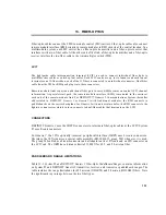
Figure 10-2, 7-Module System Wall-Mounted on Type-2 Frames, shows a possible arrangement
for a type-2 wall-mounted configuration requiring 12 frames. This arrangement has greater
jumper capacity and room to add another cabinet. It can be used as long as there is no need to
expand the white field. (In figure 10-2, a single cabinet represents white-field cabinets 4 through
8.)
I
Figure 10-2. 7-Module System Wall-Mounted on Type-2 Frames
Summary of Contents for 9601
Page 1: ...555 104 630 Issue 2 June 1991 DEFINITY Communications SystemGeneric 2 and System 85 Wiring ...
Page 57: ...2 34 MDF IDF DESIGN SYSTEM 85 AND DEFINITY GENERIC 2 WITH TRADITIONAL MODULES ...
Page 67: ...3 10 ELECTRICAL PROTECTION SYSTEM 85 AND DEFINITY GENERIC 2 WITH TRADITIONAL MODULES ...
Page 73: ...4 6 PORT PACKS DCP REPEATERS SYSTEM 85 AND DEFINITY GENERIC 2 WITH TRADITIONAL MODULES ...
Page 85: ...6 6 OVERVIEW DEFINITY GENERIC 2 WITH UNIVERSAL MODULES ...
Page 119: ...7 34 MDF lDF DESIGN DEFINITY GENERIC 2 WITH UNIVERSAL MODULES ...
Page 123: ...8 4 ELECTRICAL PROTECTION DEFINlTY GENERIC 2 WITH UNIVERSAL MODULES ...
Page 135: ...10 8 INSTALLATION EXAMPLE DEFINITY GENERIC 2 WITH UNIVERSAL MODULES ...
Page 139: ...11 4 BRI DEFINITY GENERIC 2 WITH UNIVERSAL MODULES ...
Page 174: ...GL 12 GLOSSARY ...