Chapter 8: Installation and Wiring
Do-more T1H Series PLC User Manual, 1st Edition, Rev. C
8-23
I/O Wiring Checklist
Use the following guidelines when wiring the base terminals in your system.
1. There is a limit to the size of wire the terminals can accept. The table on page 8-20 lists the
suggested nominal AWG for each terminal base type.
2. Always use a continuous length of wire, do not combine wires to attain a needed length.
3. Use the shortest possible wire length.
4. Use wire trays for routing where possible.
5. Avoid running wires near high-energy wiring.
6. Avoid running input wiring close to output wiring where possible.
7. To minimize voltage drops when wires must run a long distance, consider using multiple wires for
the return line.
8. Avoid running DC wiring in close proximity to AC wiring where possible.
9. Avoid creating sharp bends in the wires.
10. To reduce the risk of having a module with a blown fuse, we suggest you add external fuses to
your I/O wiring. A fast blow fuse, with a lower current rating than the I/O module fuse can be
added to each common, or a fuse with a rating of slightly less than the maximum current per
output point can be added to each output.
Output Module Fusing
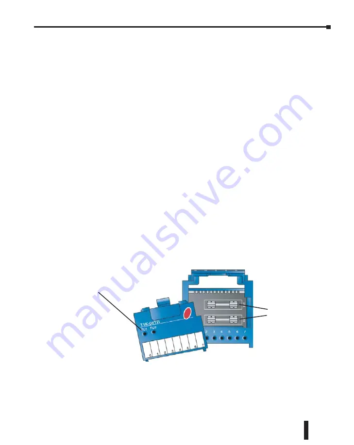
All Terminator I/O discrete output modules have internal user–replaceable fuses. For fuse
specifications and part numbers for a specific output module, refer to the output module
specifications in Chapter 5. Be sure to remove system power before attempting to remove the
I/O module from its base.
Fuses located under top cover of output modules
Replaceable
Fuses
Note:
A blown fuse indicator
illuminates only when a fuse is
blown and associated output point
is turned ON by the program.


