Chapter 8: Installation and Wiring
Do-more T1H Series PLC User Manual, 1st Edition, Rev. C
8-3
Three Levels of Protection
The publications mentioned provide many ideas and requirements for system safety. At
a minimum, you should follow these regulations. Also, you should use the following
techniques, which provide three levels of system control.
• Emergency stop switch for disconnecting system power
• Mechanical disconnect for output module power
• Orderly system shutdown sequence in the PLC control program
Emergency Stops
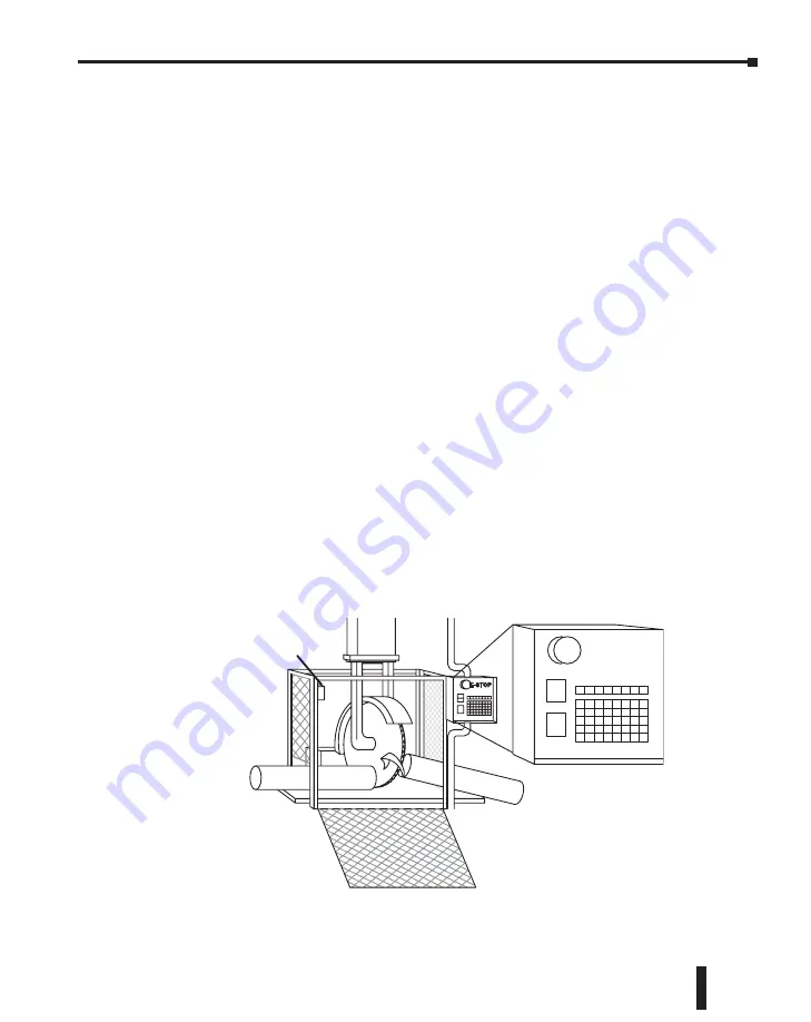
It is recommended that emergency stop circuits be incorporated into the system for every
machine controlled by a PLC. For maximum safety in a PLC system, these circuits must not
be wired into the controller, but should be hardwired external to the PLC. The emergency
stop switches should be easily accessed by the operator and are generally wired into a master
control relay (MCR) or a safety control relay (SCR) that will remove power from the PLC
I/O system in an emergency.
MCRs and SCRs provide a convenient means for removing power from the I/O system
during an emergency situation. By de-energizing an MCR (or SCR) coil, power to the input
(optional) and output devices is removed. This event occurs when any emergency stop switch
opens. However, the PLC continues to receive power and operate even though all its inputs
and outputs are disabled.
The MCR circuit could be extended by placing a PLC fault relay (closed during normal
PLC operation) in series with any other emergency stop conditions. This would cause
the MCR circuit to drop the PLC I/O power in case of a PLC failure (memory error, I/O
communications error, etc.).
Emergency
Stop
Guard Line Switch


