INITIAL ELECTRICAL INSTALLATION
CAUTION:
CABLES WHICH HAVE A GREEN / YELLOW COLOURED INSULATION
ARE FOR EARTHING PURPOSES ONLY. NEVER USE THESE CABLES FOR ANY OTHER PURPOSE.
STEP 1. WIRING MOTORS AND LIMITS SWITCHES
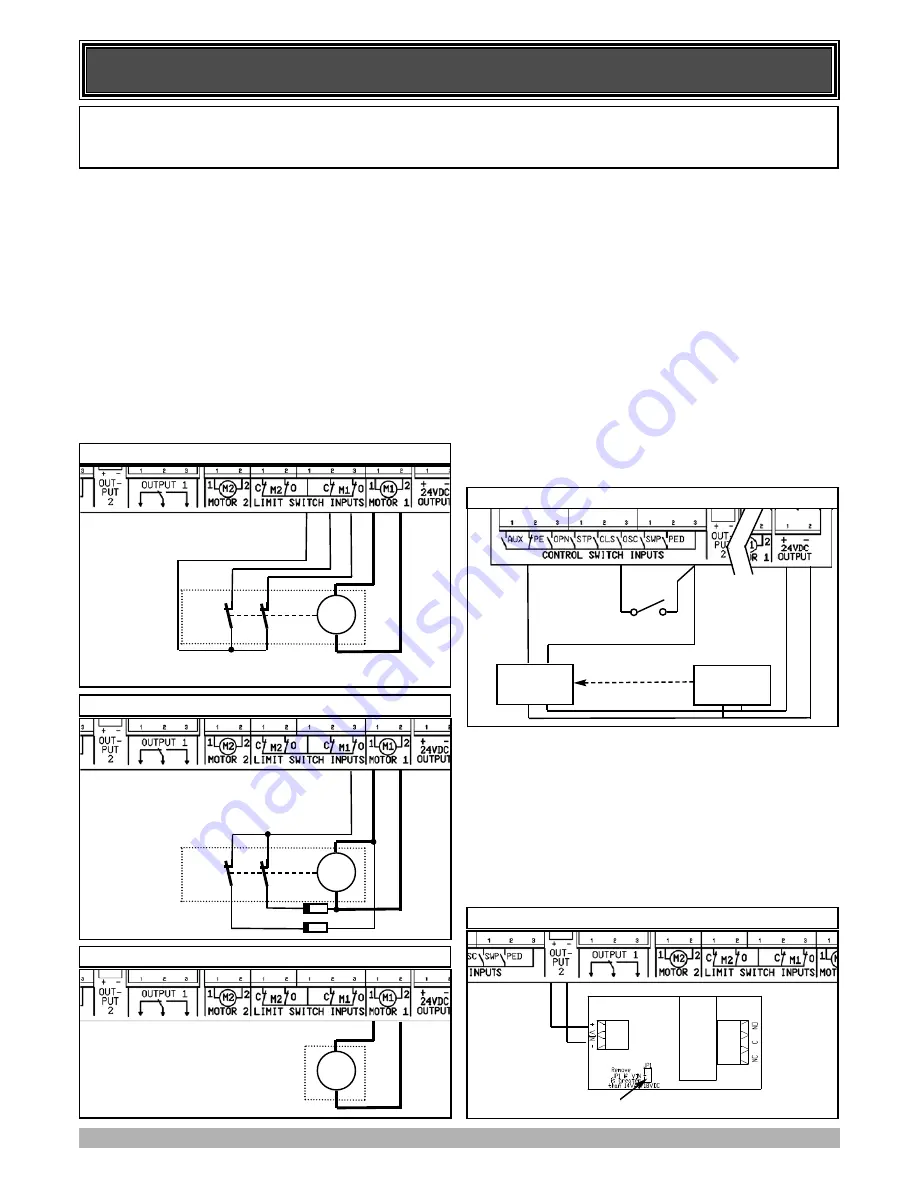
The CB-19 can be connected to the gate drive units in one of sev-
eral ways. The figures below show the various wiring methods
used for different drive unit types. Select the appropriate method
for your drive unit. Note “non-motor current carrying limit-
switch” type drive units can be connected using the standard 5
wire connections or a special 3 wire method that uses a single
limit switch sense wire and two diodes. If two drive units are
used, repeat the wiring for the second motor using the MOTOR 2
terminals. Note the drive unit connected to the MOTOR 1 termi-
nals will open first and will be used for pedrestrian access. The
motor travel direction can be reversed by swapping the motor
connections. An opportunity to confirm the correct motor polari-
ty is provided during the limit setup proceedure.
STEP 2. INSTALLING ANTENNA
Mount the antenna at the highest available position for optimal
reception. Connect the signal and ground wires of the antenna
coaxial cable to the CB-19’s antenna connector. Do not cut the
coaxial cable.
STEP 3. WIRING CONTROL SWITCH INPUTS
When remote control operation is only required the CB-19’s con-
trol switch inputs are not utilised. It is, however, strongly advised
that a Photo-electric Safety Beam be used to prevent the gate
being driven closed when an object is present in the gate way. The
other console switch inputs may be used for operating the gate via
any device that provides and switch contact output. The figure
below shows how to connect a Photo-electric Beam to the CB-19.
Note the P.E LINK jumper must be removed when the PE input is
used. The figure also shows the connections for a switch connect-
ed to the OSC control input.
STEP 4. WIRING OUTPUT1 AND OUTPUT2
Outputs 1 and 2 are used to control a lock and a light. Which out-
put is to control which function and the way it is controlled is pro-
grammable.
If using these outputs make sure that the functions
are configured for correct operation prior to setting the trav-
el limits
. OUTPUT1 is a relay output with high current capabili-
ty. OUTPUT2 is used to activate an optional external relay mod-
ule (RO-1) which in turn is used to switch the load (see figure
below).
M1
OPEN
CLOSE
M1
OPEN
CLOSE
1N4004 Diodes
Limit Switch Drive Unit Using 5 Wires
Limit Switch Drive Unit Using Special 3 Wire Method
M1
Mechnical Stop and Slip Clutch Drive Units
6
Wiring Control Switch Inputs
TRANSMITTER
Power input
output
RECEIVER
Power input
Photo-electric Beam
Connection of RO-1 to OUTPUT 2
Remove Link
RO1-101


