background image

SAFETY AND MAINTENANCE MANUAL


1NO0055UK-00 

PIAF 10

E


60 

DANGER 

BEFORE ANY MAINTENANCE, ENSURE 
THE 

ELECTRIC 

SYSTEM 

IS 

DISCONNECTED  FROM  THE  POWER 
SUPPLY. 


2.1. HYDRAULIC POWER UNIT 

 
DESCRIPTION 
 
The machine is fitted with a power unit consisting of 
a pump and a 24V fan-cooled motor. It is located on 
the left hand side of the machine. 
 
GENERAL MAINTENANCE 
 
Gear  hydraulic  pumps  deliver  reliable  performance  over  a  long  period  of  time  if  operating  in  a 
properly  maintained  system.  This  includes  using  clean  oil  of  correct  grade,  regular  filter 
replacement,  and  frequent  inspections  of  the  system  components.  If  a  pump  fails,  it  is  however 
important to determine all the causes and eliminate them to prevent repeated breakdowns. 
 

GENERAL INFORMATION  

 
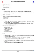
ABRASIVE WEAR CAUSED BY FINE PARTICLES 
 
Abrasive wear caused by fine particles is the most frequent cause of pump failure. Its symptom is 
a gradual reduction in power and therefore of the 

machine’s performances. Fine particles or other 

foreign bodies  circulating through the system cause wear on all components  and can be noticed 
on pressure plates, housings and shaft bearing areas. Always clean tank caps, funnels and areas 
around  the  filler  neck  before  opening  the  tank.  Cap  every  disconnected  hose,  fitting  and  various 
openings. 
 
AERATION OR CAVITATION 
 
Aeration occurs when air mixes with the oil. Air can enter the system through a small suction leak 
or by agitation of the oil surface in the tank. Surface agitation occurs when the return oil is dumped 
back above the oil level. This can occur when the oil level is too low.  
 
Cavitation is the formation and collapse of vapour bubbles in the oil. This is the result of restricted 
pump suction. Cavitation occurs usually when the oil is cold. A pump either cavitating or function 
with aerated fluid is noisy and the system functions in a jerky manner. 
 
LACK OF OIL 
 
When  a failure  is  due to  lack  of oil,  deteriorations  are  usually  quick.  This  kind  of  breakdown  can 
occur for two reasons;  
(a)  the oil level is low in the tank, or (b) there is a leak in the suction hose. 


Summary of Contents for PIAF 10E 2018

Page 1: ...2018 Lieu Dit Bacqu rue Andr Thevet 47400 FAUILLET FRANCE T l 33 0 5 53 79 80 60 Fax 33 0 5 53 79 96 90 Email contact atnplatforms com www atnplatforms com Safety and Maintenance Manual Translation of...

Page 2: ...SAFETY AND MAINTENANCE MANUAL 1NO0055UK 00 PIAF 10E 2 DISTRIBUTOR STAMP...

Page 3: ...OF MACHINE AN UNTRAINED OPERATOR PUTS HIMSELF AND OTHERS AT RISK OF DEATH OR SERIOUS INJURIES DANGER IN WORK MODE THE PLATFORM CAN ONLY BE DRIVEN ON HARD AND HORIZONTAL GROUNDS FREE FROM ANY OBSTACLE...

Page 4: ...enance Respect of these maintenance operations will give you years of trouble free operation The maintenance procedures are supplied in this manual in the MAINTENANCE Chapter The information in this m...

Page 5: ...ll four wheels must be in permanent contact with the ground The load must be distributed in the platform and cannot exceed the rated load determined by the manufacturer whatever the position of the ma...

Page 6: ...Y AND MAINTENANCE MANUAL 1NO0055UK 00 PIAF 10E 6 DANGER DO NOT USE THIS MACHINE IF YOU HAVE NOT BEEN TRAINED TO ITS SAFE OPERATION DANGER READ THE OPERATOR S AND SAFETY MANUAL BEFORE OPERATING THE MAC...

Page 7: ...m the factory This guarantee replaces any other explicit or implicit guarantee and the obligation and the responsibility of the Manufacturer in the terms of this guarantee exclude the transport charge...

Page 8: ...SAFETY AND MAINTENANCE MANUAL 1NO0055UK 00 PIAF 10E 8...

Page 9: ...n PIAF 10E Serial number P10xx meets all of the relevant provisions in the appendix at the end of the 1st chapter in book III of the fourth section of the employment code Machine Directive 2006 42 CE...

Page 10: ...SAFETY AND MAINTENANCE MANUAL 1NO0055UK 00 PIAF 10E 10...

Page 11: ...2 3 MACHINE STABILITY 21 2 4 FALLING HAZARD 22 2 5 CRUSHING HAZARD 22 2 6 ELECTROCUTION HAZARD 22 2 7 OPERATING LIMITATIONS 23 2 8 MAINTENANCE 23 SECTION 3 PREPARATION AND INSPECTION 25 3 1 INSPECTION...

Page 12: ...5 STRUCTURE 57 1 6 TORQUE VALUES 59 SECTION 2 HYDRAULICS 60 2 1 HYDRAULIC POWER UNIT 60 2 2 LUBRICATION 64 2 3 HYDRAULIC SCHEMATIC 66 SECTION 3 ELECTRICS 67 3 1 BATTERIES 67 3 2 CHARGER 70 3 3 BATTER...

Page 13: ...SAFETY AND MAINTENANCE MANUAL 1NO0055UK 00 PIAF 10E 13 Chapter I OPERATION AND SAFETY...

Page 14: ...SAFETY AND MAINTENANCE MANUAL 1NO0055UK 00 PIAF 10E 14...

Page 15: ...eight Telescopic mast Upper control station Steering wheels Braked driving wheels Hydraulic power unit Lower control station Basket work platform FRONT REAR 9 92 1 m 3 m 2 m 1 m 2 m 3 m 4 m 4 m 3 51 1...

Page 16: ...SAFETY AND MAINTENANCE MANUAL 1NO0055UK 00 PIAF 10E 16 9 92 1 m 3 m 2 m 1 m 2 m 3 m 4 m 4 m 3 51 1 m 3 m 2 m 4 m 10 m 6 m 5 m 7 m 8 m 9 m 11 m 6 55 5 18 7 92 178 4 m 3 m...

Page 17: ...Max manual force 400 N wind 0 ou 200 N wind 45 Gradeability machine lowered 25 Max tilt 2 Max wind 0 Km h for 2 persons 45 Km h for 1 person Sound level below 70 dB Power Power unit 24Vcc Energy Elect...

Page 18: ...SAFETY AND MAINTENANCE MANUAL 1NO0055UK 00 PIAF 10E 18...

Page 19: ...r important operating condition DECALS All the decals with these symbols invite you to consult the Operator and Safety manual for more details WARNING INDICATES A PROCEDURE OR OPERATION TO BE FOLLOWED...

Page 20: ...get a false sense of safety when operating the machine Control devices and alarms are there to help you NOT TO steer the machine You the operator are the only one responsible for your safety and that...

Page 21: ...CRANE NEVER ADD ANYTHING ON THE MACHINE THAT COULD INCREASE WIND LOAD SUCH AS DISPLAY PANELS You must wear appropriate clothing and the necessary protection equipment helmet harness gloves required by...

Page 22: ...on any other object in the platform Never access or exit the platform if it is not fully lowered It is recommended to wear a safety harness to prevent any falling hazard 2 5 CRUSHING HAZARD Always be...

Page 23: ...ment External manual force 400 N Max tilt 2 Max sloope 25 machine lowered Temperature range 20 C 60 C Max wind speed 45 Km h 1 person 120Kg equipment 200 Kg 0 Km h 2 persons 40 Kg equipment 200 Kg 2 8...

Page 24: ...SAFETY AND MAINTENANCE MANUAL 1NO0055UK 00 PIAF 10E 24...

Page 25: ...gibility of the safety stickers Clean or replace any illegible stickers 4 Check that there is a copy of the operator and safety manual in the working platform s document holder 5 Carry out the inspect...

Page 26: ...sition The validation pedal is correctly attached and is operating correctly The emergency stop switch is operating correctly 3 3 OPERATING CONTROLS Machine operation See Section 4 Operation Ground co...

Page 27: ...r tamper with the machine when the platform is occupied with the exception of emergency cases where it is impossible to lower and exit the platform 4 1 CONTROL STATIONS This section describes the oper...

Page 28: ...s switch to control the Up Down movement of the Jib 6 Battery hour meter discharge indicator This is an indicator light which indicates the state of charge of the battery and counts the operating hour...

Page 29: ...1 1 Control joystick for Jib Up Down structure rotation movements 2 Control joystick for drive and steering movements 3 Mast Up Down control switch 4 Horn 5 Emergency stop switch 6 Max tilt indicator...

Page 30: ...hine forwards or pull the lever backwards to reverse the machine Press on the switch on top of the joystick to the right or to the left to steer the wheels in the corresponding direction NOTE Black ar...

Page 31: ...mast sections NOTE The mast lowering movement stops when this indicator lights up To restore the functions it is necessary to first analyse and solve the problem The mast must then be raised 9 Valida...

Page 32: ...he structure can be rotated the mast or jib can be lowered using the breakdown controls 4 2 1 STRUCTURE MANUAL ROTATION 1 Open the tap on the manifold to disengage the structure rotation motor 2 Opera...

Page 33: ...is operated It is a proportional control the more it is pushed in the quicker the movement 4 2 3 JIB MANUAL LOWERING CONTROL The jib manual lowering control is located on the solenoid of the jib cyli...

Page 34: ...the machine and the brake light will come on Before the switch is actuated ensure the machine is lowered the wheels are blocked or the machine is already attached to the towing vehicle NOTE Releasing...

Page 35: ...n incline of 2 in relation to the horizontal the sensor actuates the buzzer The corresponding indicator on the upper electrical box lights up Actuation of these alarms indicates the machine has reache...

Page 36: ...an overload detection safety system The overload is detected by a mechanical system located on the platform support All the machine s movements will stop when an overload is detected The corresponding...

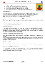
Page 37: ...he charger must be unplugged from the mains CHARGING CURVE The charging cycle starts as soon as the charger is connected to the power supply The charge may not start if the battery voltage is below 9V...

Page 38: ...R NOTE The following controls must be done on each sensor at each chain stage Wedge a block between the actuator and the sensor to actuate the sensor Check the emergency stop switches are pulled out T...

Page 39: ...ing on a slope ensure its grade is lower than 25 The platform must be fully lowered in slow speed and the basket must always be on the lower side of the slope 4 5 2 USING A TAILGATE 4 5 3 USING A FORK...

Page 40: ...MACHINE Prior to any operation check the capacity of the equipment used min 3000 Kg 4 5 6 TIE DOWN ON THE BED OF A TRUCK The machine must be tied down to ensure stability during transportation Chock...

Page 41: ...N FRANCE Conformity to the decree from March 1st 2004 The machine must be controlled every 6 months by an accredited body This verification consist of check of its state of condition Operation tests b...

Page 42: ...SAFETY AND MAINTENANCE MANUAL 1NO0055UK 00 PIAF 10E 42...

Page 43: ...SAFETY AND MAINTENANCE MANUAL 1NO0055UK 00 PIAF 10E 43 Chapter II MAINTENANCE...

Page 44: ...SAFETY AND MAINTENANCE MANUAL 1NO0055UK 00 PIAF 10E 44...

Page 45: ...11 STEERING PIVOT PIN 2 12 ANGLE SENSOR RS70 1 13 FLANGED BUSHING 15 17 23 H15 2 14 WHEEL 16 5 10 NM 5 94 140 3 15 P10E STEERING CYLINDER 1 16 BOLT CHC M06X20 8 8 ZI FT 4 17 BOLT CHC M08X30 8 8 ZI FT...

Page 46: ...under the chassis to support the platform s weight Lower the chassis on the block 5 Unscrew the bolts nuts and remove the wheel s NOTE All 4 wheels are identical and therefore interchangeable INSTALL...

Page 47: ...safety bolt 19 and the nut 22 to drive the steering cylinder pin 7 22 Drive the pivot pin 11 out from the top or bottom depending on your equipment or preference 23 Release the steering pivot 3 and th...

Page 48: ...installation the sensor must be positioned as near as possible to 85 middle position with the wheel straight parallel to the chassis length 15 Place the sensor 12 on its support 4 perpendicular to its...

Page 49: ...t where the slewing is produced by a turntable bearing with worm gear coupled to a hydraulic motor Adequate lubrication will guarantee a long service life for the bearing and gear teeth LUBRICATION FR...

Page 50: ...erating hours SURVEILLANCE OF THE ROTATION During cleaning prior to greasing the teeth Check carefully for the absence of foreign bodies in the teeth turntable and sprocket Check the evenness of the l...

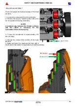
Page 51: ...roller pins Do not suppress the play completely NOTE A minimum play between the friction surfaces and the rollers is necessary for the mechanism to function properly 3 Torque the counternuts to approx...

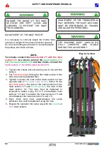
Page 52: ...d one must be adjusted first 3 Tighten or loosen the nuts on the chain anchors on the opposite side of the chain slack sensor that is for the first chain system the nuts on the chain anchors on the ma...

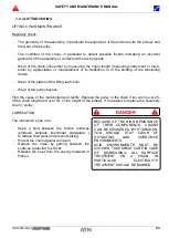
Page 53: ...y of the assembly or contacts with structure parts Wear of the chain links either by measuring the chain length measuring instrument or ruler either by appreciation or measurement of its deflection or...

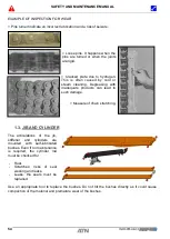
Page 54: ...egreasing with inadequate products can lead to such damage Measure of chain stretching 1 3 JIB AND CYLINDER The articulations of the jib stiffener and cylinders are mounted with self lubricated bushes...

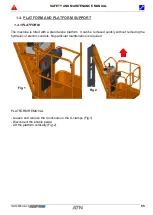
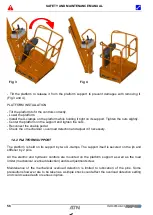
Page 55: ...machine is fitted with a stand alone platform It can be removed quickly without removing the hydraulic or electric controls No particular maintenance is required PLATFORM REMOVAL Loosen and remove the...

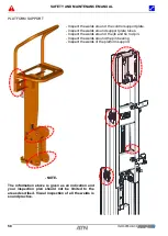
Page 56: ...nable pedal Check the mechanical overload detection and adjust it if necessary 1 4 2 PLATFORM SUPPORT The platform is held on its support by two U clamps The support itself is secured on the jib and s...

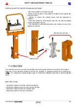
Page 57: ...cut out 15 tolerance is admissible therefore the maximum load in the platform is 230 Kg 1 5 STRUCTURE The machine structure is made of all welded steel with special profiles and specific steel grades...

Page 58: ...ds around support plate tubes Inspect the welds around the jib and tie rod pin Inspect the welds around the pin bearing Inspect the welds of the platform support NOTE The information above is given as...

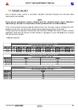
Page 59: ...lvanized bichromate Torque wrenches are precision instruments and should be handled with care to ensure accurate calibration Each time the wrench is either blocked or damaged it must immediately be re...

Page 60: ...the machine s performances Fine particles or other foreign bodies circulating through the system cause wear on all components and can be noticed on pressure plates housings and shaft bearing areas Alw...

Page 61: ...OUBLESHOOTING IF A PUMP IS NOISY CAVITATION Oil level too low Air gets into the system through the shaft seal Oil too heavy Air leak Restriction in the suction line Worn pump NOTE Use a pressure gauge...

Page 62: ...rain and fill with recommended oil Refer to the Lubrication section If oil level too low fill to correct level IF A PUMP DOES NOT DELIVER FLUID Fluid in the tank too low Restriction in the inlet line...

Page 63: ...r leak or restriction in the inlet line locate and repair the leak If the pump does not run properly check for internal damage Reassemble if correct and replace the seals Replace the pump if necessary...

Page 64: ...r the tank and remove the filling cap 3 Clean and install the drain plug on the tank with a new seal 4 Fill the reservoir with new hydraulic oil to the level indicated on the tank 2 2 LUBRICATION 2 2...

Page 65: ...ration Occasional lubrication After each pressure wash Hydraulic reservoir Oil Oil type HYDRO 46 USA FLUID PEL 6 Europe Circuit capacity 5 litres Tank capacity 6 litres Oil change intervals 250 hours...

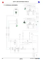
Page 66: ...SAFETY AND MAINTENANCE MANUAL 1NO0055UK 00 PIAF 10E 66 2 3 HYDRAULIC SCHEMATIC...

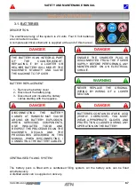
Page 67: ...EN DISCONNECTING CONNECTING THE BATTERY CABLES DANGER BATTERIES CONTAIN SULFURIC ACID HIGHLY CORROSIVE YOU MUST WEAR APPROPRIATE GLOVES AND PROTECTION GLASSES DURING ANY OPERATION ON THE BATTERY 3 1 B...

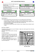
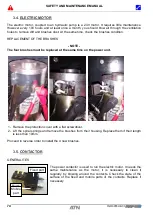
Page 68: ...l flow to flush out all the dirt that could obstruct the filter cone Check the hose for flexibility Check the level indicator caps ensure the float is mobile Replace the level indicator caps if clogge...

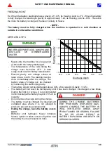
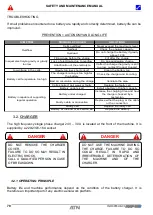
Page 69: ...the battery discharged The temperature of the cells during the charge must be below 45 C A heat surge could result in battery deterioration Record gravity and voltage values at least once a month The...

Page 70: ...ed the maximum level Overheat Check the charger capacity Overload Do not charge the battery if gravity above 1 230 Filling done before the charge Fill after the charge Loss of electrolyte due to overf...

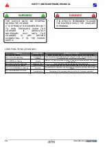
Page 71: ...harge lasts longer than 15 hours This fault appears when a battery cell is faulty short circuit or when the ambient temperature is too high Check the battery condition To resume charge disconnect from...

Page 72: ...xcess of the maximum allowed check the capacity of the battery BIP RED YELLOW Led flashing Battery current Loss of output current control fault on the control logic BIP RED GREEN Led flashing Battery...

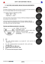
Page 73: ...machine is switched on the LCD screen displays briefly the hourmeter When a fault is detected by the controller the screen displays the error code and the red LED above flashes Technical specificatio...

Page 74: ...he four brushes must be replaced at the same time on the power unit 1 Remove the protection cover with a flat screwdriver 2 Lift the spiral springs and remove the brushes from their housing Replace th...

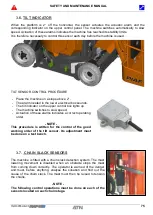
Page 75: ...s The tilt indicator on the upper control box lights up The machine switches to slow speed Actuation of these alarms indicates a correct operating order NOTE This procedure is written for the control...

Page 76: ...cal system When the overload is detected all the movements of the machines are disabled To restore the functions the platform must be unloaded until the buzzer stops and the corresponding indicator on...

Page 77: ...st M Pumps Bolt tightening W Leak check D Electrical components Control of the good working condition of the horn D Machine switches to slow speed when elevated D Chain slack sensor control D Overload...

Page 78: ...SAFETY AND MAINTENANCE MANUAL 1NO0055UK 00 PIAF 10E 78 3 10 ELECTRIC SCHEMATIC...

Page 79: ...SAFETY AND MAINTENANCE MANUAL 1NO0055UK 00 PIAF 10E 79...

Page 80: ...SAFETY AND MAINTENANCE MANUAL 1NO0055UK 00 PIAF 10E 80 NOTES...

Page 81: ...SAFETY AND MAINTENANCE MANUAL 1NO0055UK 00 PIAF 10E 81 NOTES...

Reviews: