SAFETY AND MAINTENANCE MANUAL
1NO0055UK-00
PIAF 10
E
47
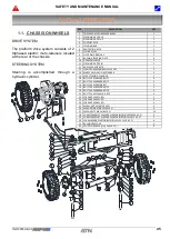
REMOVAL OF THE STEERING BAR (5).
9- Remove the split pins (32) and washers (28).
10-Release the steering bar (5).
REMOVAL OF THE ANGLE SENSOR (12)
11- Loosen the bolts (19) and washers (29) securing the sensor protection cover (6).
12- Remove the angle sensor (12) and its pin (10). Disconnect the connector.
13- If necessary, you can remove the sensor support (4) by removing the bolts (20) and washers
(27).
REMOVAL OF THE RHS STEERING PIVOT (2).
14- Remove the nut on the pivot pin (24) and remove the washer (27) and the bolt (18).
15- Drive the pivot pin (11) out from the top or bottom depending on your equipment or preference.
16- Release the steering pivot (2).
17- The washers (8) should have a thickness of 3mm minimum. Replace them if necessary.
18- You can also remove the flanges on the wheel pins (9) if the washer (8) is completely worn
and the pivots (2 and 3) started rubbing on the flanges: Unscrew the bolts (20), then the flanges
(9).
19- Replace if necessary the pivot bushes (31) in the flanges (9).
- NOTE -
To remove the steering cylinder (15), the LHS pivot must be dismantled (3).
REMOVAL OF THE LHS PIVOT (3).
20- Remove the nut on the pivot pin (24) and remove the washer (27) and the bolt (18).
21- Unscrew the pin safety bolt (19) and the nut (22) to drive the steering cylinder pin (7).
22- Drive the pivot pin (11) out from the top or bottom depending on your equipment or preference.
23- Release the steering pivot (3) and the steering cylinder (15).
24- Remove the split pin (32) and the washer (28) to release the steering cylinder (15) from the
steering pivot (3).
25- Disconnect the hoses from the steering cylinder (5) if you need to replace it and cap the ports
to prevent any oil spill.
INSTALLATION OF THE STEERING CYLINDER (15) AND LHS PIVOT (3).
1- Install new bushes (31) on the flanges (9) if necessary.
2- Replace the steering cylinder (15) on the pin of the LHS steering pivot (3).
3- Secure it with the washer (28) and the split pin (32).
4- Install a new thrust washer (8) if necessary on top of the pivot (3). You can hold it in place more
easily with grease.
5- Install the assembly (pivot + cylinder) on the chassis with the pivot pin (11). Ensure the middle
hole of the pivot pin is in line with the hole from the pivot square.
6- Secure the pivot pin (11) with the bolt (18) washer (27) and nut (24).
7- Reconnect the hoses on the steering cylinder if necessary.
8- Install the pin (7) on the steering cylinder barrel side and secure it with the bolt (19) and the nut
(22).
INSTALLATION OF THE RHS PIVOT (2).
9- Install new bushes (31) on the flange (9) if necessary.
10- Install a new thrust washer (8) if necessary on top of the pivot (3). You can hold it in place
more easily with grease.
Summary of Contents for PIAF 10E 2018
Page 2: ...SAFETY AND MAINTENANCE MANUAL 1NO0055UK 00 PIAF 10E 2 DISTRIBUTOR STAMP...
Page 8: ...SAFETY AND MAINTENANCE MANUAL 1NO0055UK 00 PIAF 10E 8...
Page 10: ...SAFETY AND MAINTENANCE MANUAL 1NO0055UK 00 PIAF 10E 10...
Page 13: ...SAFETY AND MAINTENANCE MANUAL 1NO0055UK 00 PIAF 10E 13 Chapter I OPERATION AND SAFETY...
Page 14: ...SAFETY AND MAINTENANCE MANUAL 1NO0055UK 00 PIAF 10E 14...
Page 18: ...SAFETY AND MAINTENANCE MANUAL 1NO0055UK 00 PIAF 10E 18...
Page 24: ...SAFETY AND MAINTENANCE MANUAL 1NO0055UK 00 PIAF 10E 24...
Page 42: ...SAFETY AND MAINTENANCE MANUAL 1NO0055UK 00 PIAF 10E 42...
Page 43: ...SAFETY AND MAINTENANCE MANUAL 1NO0055UK 00 PIAF 10E 43 Chapter II MAINTENANCE...
Page 44: ...SAFETY AND MAINTENANCE MANUAL 1NO0055UK 00 PIAF 10E 44...
Page 66: ...SAFETY AND MAINTENANCE MANUAL 1NO0055UK 00 PIAF 10E 66 2 3 HYDRAULIC SCHEMATIC...
Page 78: ...SAFETY AND MAINTENANCE MANUAL 1NO0055UK 00 PIAF 10E 78 3 10 ELECTRIC SCHEMATIC...
Page 79: ...SAFETY AND MAINTENANCE MANUAL 1NO0055UK 00 PIAF 10E 79...
Page 80: ...SAFETY AND MAINTENANCE MANUAL 1NO0055UK 00 PIAF 10E 80 NOTES...
Page 81: ...SAFETY AND MAINTENANCE MANUAL 1NO0055UK 00 PIAF 10E 81 NOTES...

