


ASUS RS500-E9 Series
4-19
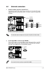
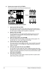
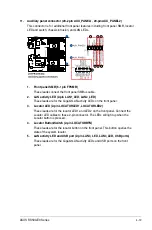
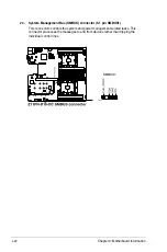
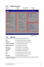
11. Auxiliary panel connector (20-2 pin AUX_PANEL1, 20-pin AUX_PANEL2)
This connector is for additional front panel features including front panel SMB, locator
LED and switch, chassis intrusion, and LAN LEDs.
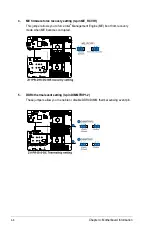
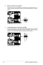
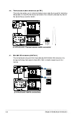
1. Front panel SMB (6-1 pin FPSMB)
These leads connect the front panel SMBus cable.
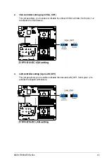
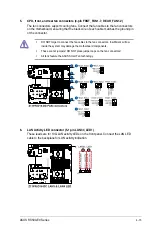
2. LAN activity LED (2-pin LAN1_LED, LAN2_LED)
These leads are for the Gigabit LAN activity LEDs on the front panel.
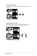
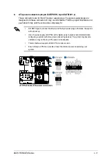
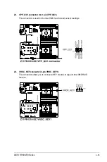
3. Locator LED (2-pin LOCATORLED1, LOCATORLED2)
These leads are for the locator LED1 and LED2 on the front panel. Connect the
Locator LED cables to these 2-pin connector. The LEDs will light up when the
Locator button is pressed.
4. Locator Button/Switch (2-pin LOCATORBTN)
These leads are for the locator button on the front panel. This button queries the
state of the system locator.
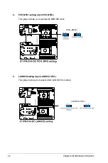
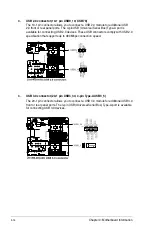
5. LAN activity LED and USB port (2-pin LAN3_LED, LAN4_LED, USB ports)
These leads are for the Gigabit LAN activity LEDs and USB ports on the front
panel.
Summary of Contents for RS500-E9 Series
Page 1: ...1U Rackmount Server User Guide RS500 E9 Series RS500 E9 PS4 RS500 E9 RS4 RS500 E9 RS4 U ...
Page 10: ...x ...
Page 25: ...2 5 ASUS RS500 E9 Series 6 Reinstall the air ducts CPU1 CPU socket 1 CPU2 CPU socket 2 ...
Page 51: ...3 5 ASUS RS500 E9 Series 3 2 Rail kit dimensions 589mm 43 6mm 900mm 43 6mm ...
Page 52: ...Chapter 3 Installation Options 3 6 ...
Page 54: ...Chapter 4 Motherboard Information 4 2 4 1 Motherboard layout ...
Page 148: ...6 22 Chapter 6 RAID Configuration ...
Page 155: ...7 7 ASUS RS500 E9 Series 5 Follow the onscreen instructions to complete the installation ...
Page 156: ...7 8 Chapter 7 Driver Installation ...
Page 157: ...Appendix Appendix ...
Page 158: ...Z11PR D16 DC block diagram ...