


ASUS RS500-E9 Series
1-7
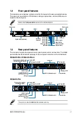
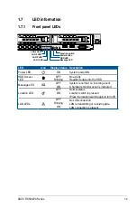
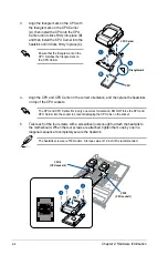
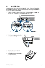
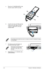
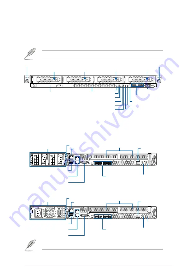
1.4
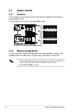
Front panel features
The barebone server displays a simple yet stylish front panel with easily accessible features.
The power and reset buttons, LED indicators, slim type optical drive, and two USB ports are
located on the front panel.
Refer to the
Front panel LEDs
section for the LED descriptions.
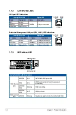
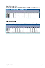
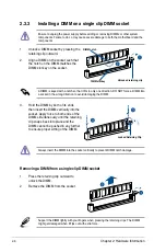
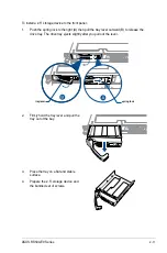
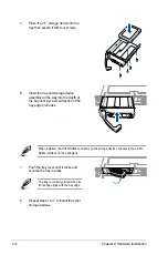
1.5
Rear panel features
The rear panel includes the expansion slots, system power socket, and rear fans. The middle
part includes the I/O shield with openings for the rear panel connectors on the motherboard.
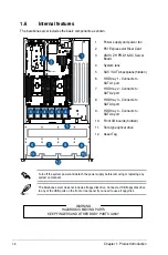
4
3
2
1
Optical drive (optional)
Asset tag
(hidden)
Rack screw
Rack screw
USB 3.0 ports
VGA port
LAN 2 LED
LAN 1 LED
LAN 4 LED
LAN 3 LED
Message LED
Power button
Location switch
Reset button
HDD LED
HDD 1
HDD 2
HDD 3
HDD 4
*This port is for ASUS ASMB9-iKVM controller card only.
RS500-E9-RS4 / RS500-E9-RS4-U
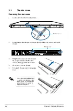
RS500-E9-PS4
VGA port
Gigabit LAN port 1
(bottom) and 2 (top)
USB 3.0 ports
LAN port for iKVM*
OCP 2.0 Mezzanine slot
Power button
Q-Code LED
Power cord connector and
Redundant power supply
Power cord connector
and power supply
VGA port
Gigabit LAN port 1
(bottom) and 2 (top)
USB 3.0 ports
LAN port for iKVM*
Message LED
Power button
Q-Code LED
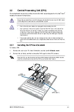
PCI-E slot
OCP 2.0 Mezzanine slot
PCI-E slot
Locate LED
Locate LED
Message LED
Summary of Contents for RS500-E9 Series
Page 1: ...1U Rackmount Server User Guide RS500 E9 Series RS500 E9 PS4 RS500 E9 RS4 RS500 E9 RS4 U ...
Page 10: ...x ...
Page 25: ...2 5 ASUS RS500 E9 Series 6 Reinstall the air ducts CPU1 CPU socket 1 CPU2 CPU socket 2 ...
Page 51: ...3 5 ASUS RS500 E9 Series 3 2 Rail kit dimensions 589mm 43 6mm 900mm 43 6mm ...
Page 52: ...Chapter 3 Installation Options 3 6 ...
Page 54: ...Chapter 4 Motherboard Information 4 2 4 1 Motherboard layout ...
Page 148: ...6 22 Chapter 6 RAID Configuration ...
Page 155: ...7 7 ASUS RS500 E9 Series 5 Follow the onscreen instructions to complete the installation ...
Page 156: ...7 8 Chapter 7 Driver Installation ...
Page 157: ...Appendix Appendix ...
Page 158: ...Z11PR D16 DC block diagram ...