


5-27
ASUS RS500-E9 Series
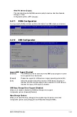
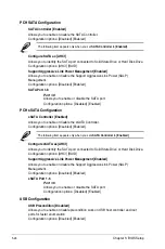
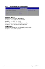
XHCI Manual Mode [Disabled]
This option is used by validation.
Configuration options: [Disabled] [Enabled]
The following items appear only when the
XHCI Manual Mode
is set to
[Enabled]
.
Trunk Clock Gating (BTCG) [Enabled]
Allows you to enable or disable BTCG.
Configuration options: [Disabled] [Enabled]
Enable USB 3.0 pins [Disable all pins]
Allows you to enable or disable USB 3.0 pins or on a per pin basis.
Configuration options: [Select Per-Pin] [Disable all pins] [Enable all pins]
USB Per-Connector Disable [Disabled]
Allows you to enable or disable each of the USB physical connectors. Once a
connector is disabled, any USB devices plugged into the connector will not be detected
by BIOS or OS.
Configuration options: [Disabled] [Enabled]
The following items appear only when the
USB Per-Connector Disable
is set to
[Enabled]
.
USB_1-9 [Enabled]
Configuration options: [Disabled] [Enabled]
USB3_1-5 [Enabled]
Configuration options: [Disabled] [Enabled]
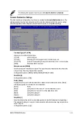
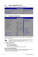
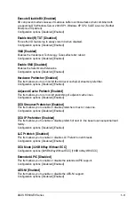
Security Configuration
SMM BIOS Write Protect [Enabled]
Allows you to enable or disable SMM BIOS Write Protect.
Configuration options: [Disabled] [Enabled]
DCI Auto Detect Enable [Disabled]
When enabled, it detects DCI being connected during BIOS POST time and enables DCI.
Configuration options: [Disabled] [Enabled]
Summary of Contents for RS500-E9 Series
Page 1: ...1U Rackmount Server User Guide RS500 E9 Series RS500 E9 PS4 RS500 E9 RS4 RS500 E9 RS4 U ...
Page 10: ...x ...
Page 25: ...2 5 ASUS RS500 E9 Series 6 Reinstall the air ducts CPU1 CPU socket 1 CPU2 CPU socket 2 ...
Page 51: ...3 5 ASUS RS500 E9 Series 3 2 Rail kit dimensions 589mm 43 6mm 900mm 43 6mm ...
Page 52: ...Chapter 3 Installation Options 3 6 ...
Page 54: ...Chapter 4 Motherboard Information 4 2 4 1 Motherboard layout ...
Page 148: ...6 22 Chapter 6 RAID Configuration ...
Page 155: ...7 7 ASUS RS500 E9 Series 5 Follow the onscreen instructions to complete the installation ...
Page 156: ...7 8 Chapter 7 Driver Installation ...
Page 157: ...Appendix Appendix ...
Page 158: ...Z11PR D16 DC block diagram ...