


Chapter 2: Hardware Information
2-12
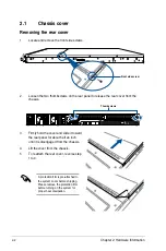
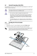
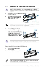
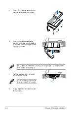
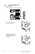
5.
Place the 2.5” storage device into the
tray then secure it with four screws.
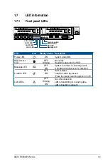
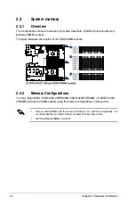
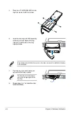
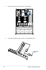
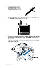
7.
Push the tray lever until it clicks and
secures the tray in place.
The tray is correctly placed when its
front edge aligns with the bay edge.
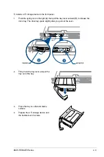
8.
Repeat steps 1 to 7 to install the other
storage devices.
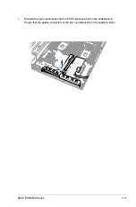
When installed, the SATA/NVMe connector on the storage device connects to the SATA/
NVMe interface on the backplane.
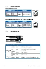
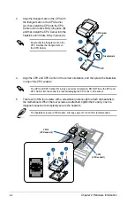
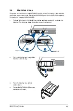
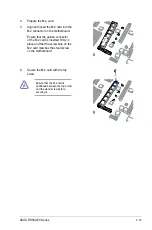
6.
Insert the tray and storage device
assembly all the way into the depth of
the bay until just a small fraction of the
tray edge protrudes.
Summary of Contents for RS500-E9 Series
Page 1: ...1U Rackmount Server User Guide RS500 E9 Series RS500 E9 PS4 RS500 E9 RS4 RS500 E9 RS4 U ...
Page 10: ...x ...
Page 25: ...2 5 ASUS RS500 E9 Series 6 Reinstall the air ducts CPU1 CPU socket 1 CPU2 CPU socket 2 ...
Page 51: ...3 5 ASUS RS500 E9 Series 3 2 Rail kit dimensions 589mm 43 6mm 900mm 43 6mm ...
Page 52: ...Chapter 3 Installation Options 3 6 ...
Page 54: ...Chapter 4 Motherboard Information 4 2 4 1 Motherboard layout ...
Page 148: ...6 22 Chapter 6 RAID Configuration ...
Page 155: ...7 7 ASUS RS500 E9 Series 5 Follow the onscreen instructions to complete the installation ...
Page 156: ...7 8 Chapter 7 Driver Installation ...
Page 157: ...Appendix Appendix ...
Page 158: ...Z11PR D16 DC block diagram ...