


EFD1000 E5 Dual Electronic Flight Instrument (EFI) Install Manual
DOCUMENT # 900-00041-001
PAGE 55-226
REVISION D
© Copyright 2019 Aspen Avionics Inc.
STEP 2 – Plan the Cutouts for the Instrument Panel in Accordance with the Cutout Location
Figures Below
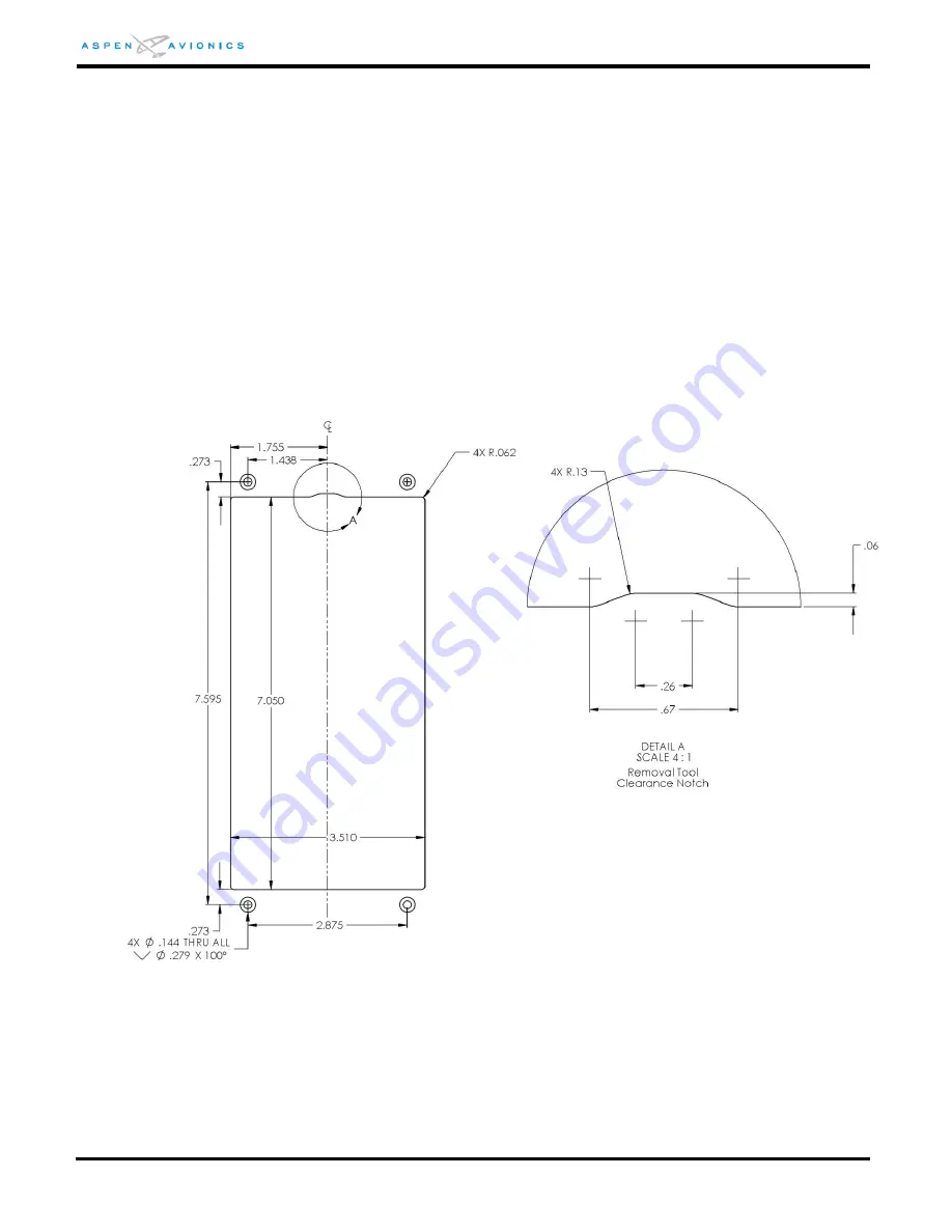
Using the dimensions from Figure 6-3 as a guide determine the mounting location of
the bracket. Verify that no supporting structure is compromised. See AC43.13-2B.
STEP 3 – Obtain the Recess Mount Kit
One Kit is required for each EFD Display.
STEP 4 – Measure and Mark the EFD Cutout and Bracket Mounting Hole Locations
Using the dimensions from Figure 6-3 as a guide mark the EFD cutout and four bracket
mounting holes.
The clearance notch at the top (see detail “A”) is to permit a tool to be inserted to press
the EFD release mechanism and release the EFD from the mounting bracket
Figure 6-3: Single Display Recess Mount Cutout (inches)
STEP 5 – Cut out the EFD hole and Drill Four Mounting Holes
1)
Remove instruments from surrounding area to be cut or remove instrument
panel from the aircraft. Verify nothing is in the way of the cutting tool before
making the cut.
2)
Cut the display bezel opening and drill four bracket mounting holes (per EFD)
0.144” in diameter and countersink as required.