EFD1000 E5 Dual Electronic Flight Instrument (EFI) Install Manual
DOCUMENT # 900-00041-001
PAGE 117-226
REVISION D
© Copyright 2019 Aspen Avionics Inc.
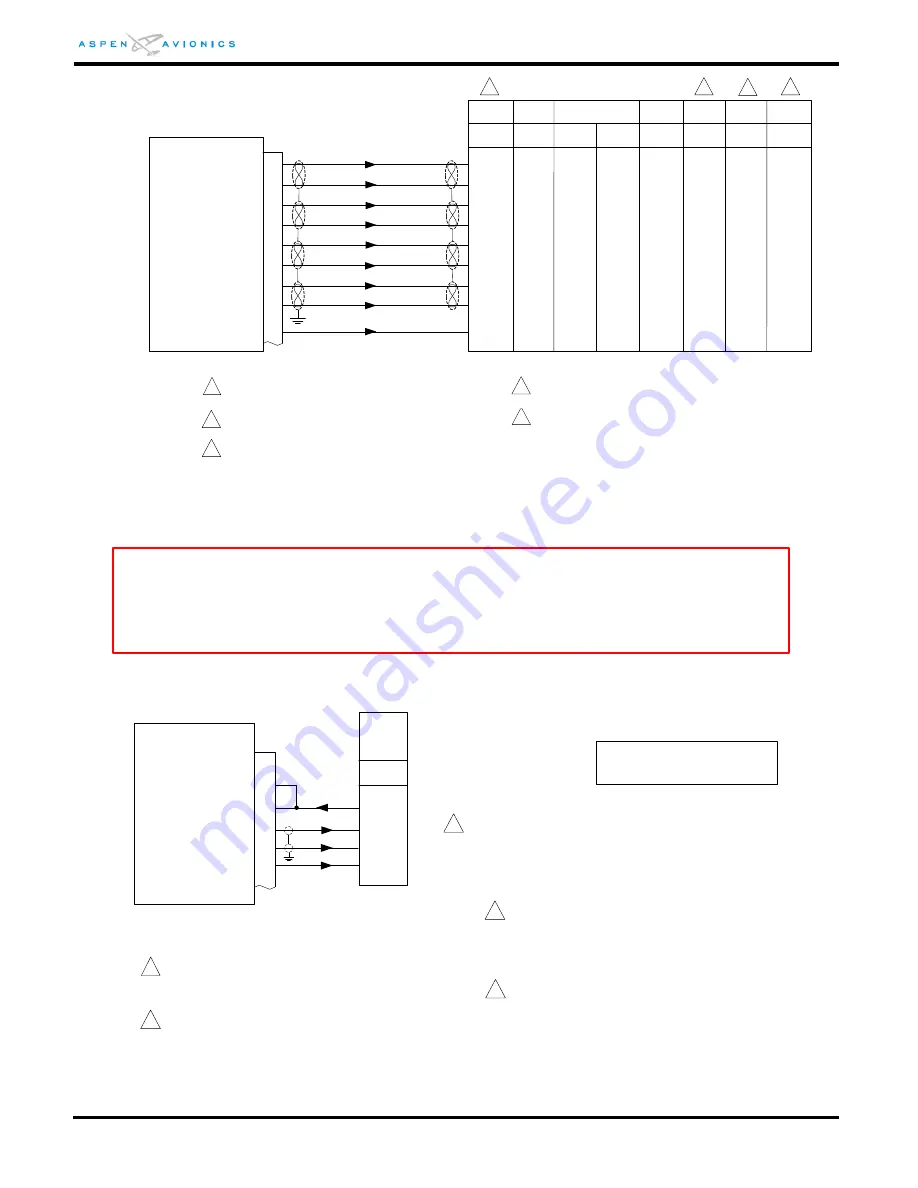
Figure 9-18: Century Autopilot to ACU Interface (minus HDG/CRS Datum)
Figure 9-18A: NSD360A Emulation (Century 21/31/41/2000/4000)
ACU
CD92
CD34
CD58
CD34
CD194
CD191
Autopilot can only be connected to ACU #1 in a
dual ACU configuration.
Century
I
Century
III
Century
IV
Century
2000/4000
Triden
CD66
5
36
17
35
16
30
11
37
18
P2
+ RIGHT
+ LEFT
+ LAT FLG
- LAT FLG
+UP
+DN
+VERT FLG
-VERT FLG
/ILS ENERGIZE
_
_
44
9
14
13
A
B
6
5
A
B
B
A
5
32
1
2
3
4
31
6
7
8
2
1
_
_
_
9
_
_
_
_
_
_
_
_
_
_
_
_
_
_
_
_
_
_
_
4
_
_
46
_
5
_
_
_
_
_
_
_
_
1
2
This note is not used
3
Century
II
_
45
Century
21
Century
31/41
2
3
7
8
4
3
1
CD191
4 Shield wires per existing autopilot specification single
shielded or twisted shielded pair.
Century I autopilot is L/R only.
5
2
*Must also make HDG/CRS connections
per Figure 9-18A, 9-18B, 9-18C, or 9-18D
3
3
3
Refer to autopilot manufacturers’ documentation for
autopilot-side integration information (including
autopilot STC compliance data) and for autopilot and
flight director checkout procedures. This drawing, as
it pertains to the non-Aspen equipment, is for
reference only.
3
CRS DATUM
23
22
11
P3
HDG DATUM
CRS/HDG COM
HDG-CRS EXT
Century
Heading
System
Adapter
CD175
2
17
20
ACU
When replacing a DC version NSD-360
If the existing DG/HSI is to remain in the aircraft
do not parallel HDG/CRS Datum with ACU.
Cap and Stow at DG/HSI or use switch.
Century
21/31
41/2000/
4000
19
25
HDG-CRS OFFSET
4.8Vdc reference
Set ACU HSI TYPE = 1
Set ACU DATUM = REVERSED
Century 21/31/41/2000/4000 should be wired per
DC Datum drawing above, if they were previously
wired AC then the ARINC Select strap needs to be
removed. The 31 requires that the 1B929 ARINC
Adapter box be removed.
1
2
Configuration Matrix
(see Section 10)
3
Interface uses 4.8Vdc reference from CD175
pin 19 ARINC Ref Low. 9.6Vdc reference not
used.
2
4
CAUTION
Damage to the ACU or autopilot computer could occur if wiring is not exactly as shown. Before connecting the
HDG and CRS Datum wiring to the autopilot computer, the HDG and CRS Datum voltages should be checked
per below. Also, if a DG was previously installed verify that the DG Select Strap - C21 (CD194-13), or C31
(CD200-32), or C41 (CD185-17), or C2000 (CD220-42), or C4000 (CD279-12) is removed (not grounded) as it
shorts the HDG and CRS inputs together.
HDG/CRS
Datum Voltage
0º
4.8Vdc
- 90º
9.6Vdc
+90º
0.1Vdc
Refer to autopilot manufacturers’ documentation for
autopilot-side integration information (including autopilot
STC compliance data) and for autopilot and flight director
checkout procedures. This drawing, as it pertains to the
non-Aspen equipment, is for reference only.


