EFD1000 E5 Dual Electronic Flight Instrument (EFI) Install Manual
DOCUMENT # 900-00041-001
PAGE 200-226
REVISION D
© Copyright 2019 Aspen Avionics Inc.
An unpainted surface of the EA100 case must be bonded to aircraft ground either through mounting to
a metal shelf or with an installer fabricated bonding strap or wire braid no more than 12 inches in
length. Attach ground lug of bonding strap to one of the mounting screws if required. Refer to AC
43.13-1B paragraphs 11-187 to 11-190, pages 11-73 to 11-79 for additional bonding information.
Verify EA-100 case to airframe ground has ≤ 3 milliohms of resistance.
Shelf or bracket fabrication is beyond the scope of this STC and will require separate FAA approved
data.
Structural DER analysis or static testing should be accomplished to the following ultimate load factors
for items of mass within the cabin or cockpit: upward and downward 10.0g, forward 18.0g, aft and
sideward 4.5g. The load factors should be multiplied by the weight of the EA100 plus any attachment
brackets and hardware. See AC43.13-2B, Chapter1 Paragraph 103, page 2 and Paragraph 105, page
3. Structural Sizing and Analysis must be accomplished for the installation location in accordance with
AC43.13-2B, Chapter1 Paragraph 104, page 2. Materials and workmanship must be accomplished in
accordance with AC43.13-2B, Chapter1 Paragraph 106, page 4.
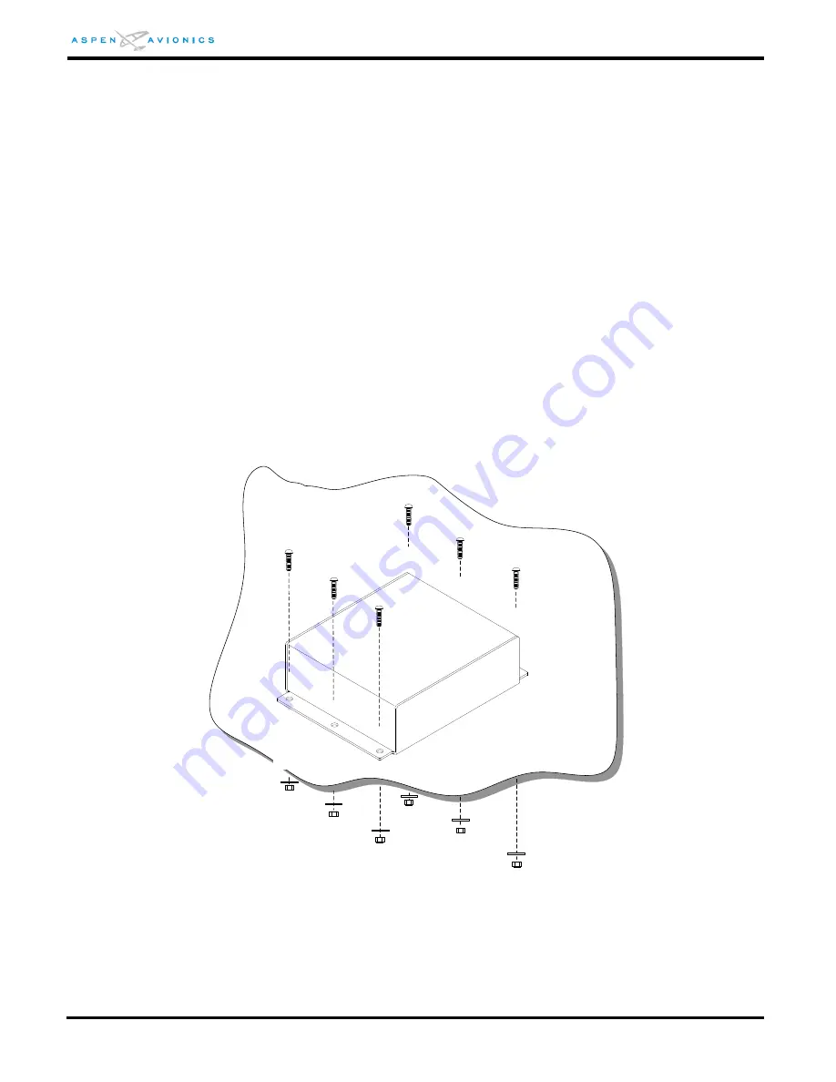
Mount the EA-100 using six (6) MS35206 #8-32 screws, six (6) NAS1149FN832P washers, and six (6)
MS21044N08 #8-32 self-locking nuts. Tighten nuts to 12 in-lbs.
Figure E4: EA100 Mounting


