


EFD1000 E5 Dual Electronic Flight Instrument (EFI) Install Manual
DOCUMENT # 900-00041-001
PAGE 144-226
REVISION D
© Copyright 2019 Aspen Avionics Inc.
10.4.6.12
Installation Menu Page – RS-232 CONFIG B
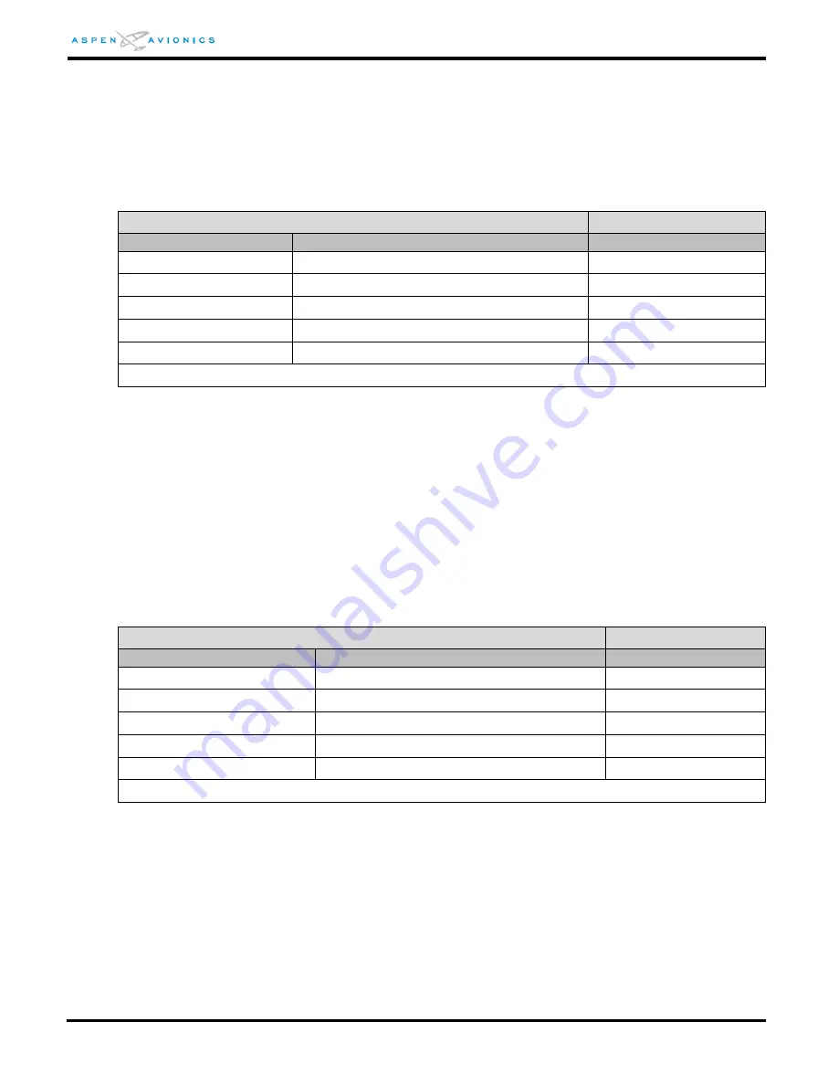
The following menu is used to configure the RS-232 RX IN 5 sensor port and the four
RS-232 TX OUT ports. Options include ADC (two types). Note - some ports do not
include all interface options. (See wiring diagrams in sections 9 to determine how
each port was wired and configure port accordingly.)
INSTALLATION MENU PAGE – RS-232 CONFIG B
Feature
Options
Actual Setting
232 IN PORT 5
NONE
232 OUT PORT 0
NONE
232 OUT PORT 1
NONE, ADC TYPE 1, ADC TYPE 2
232 OUT PORT 2
NONE, ADC TYPE 1, ADC TYPE 2
232 OUT PORT 3
NONE, ADC TYPE 1, ADC TYPE 2
Notes: ADC TYPE 1=”Z” (Shadin) format, ADC TYPE 2=”C” (Bendix King C) format
10.4.6.13
Installation Menu Page – RS-232 CONFIG C
This page is not applicable to the EFD1000 E5
10.4.6.14
Installation Menu Page – ACU CONFIG A
The following menu configures the emulation modes for the Flight Director and HDG
and CRS Datum interfaces. The installation wiring diagrams in Section 9 have a
Configuration Matrix table that will be used to set ACU HSI TYPE and ACU FD TYPE.
(See Section 10.4.7 for example).
INSTALLATION MENU PAGE – ACU CONFIG A
Feature
Options
Actual Setting
ACU HSI TYPE
0,1,2,3
ACU FD TYPE
Not applicable
ACU DATUM
NORMAL, REVERSED
FD PITCH OFFSET ADJ
Not applicable
FD ROLL OFFSET ADJ
Not applicable