


EFD1000 E5 Dual Electronic Flight Instrument (EFI) Install Manual
DOCUMENT # 900-00041-001
PAGE 33-226
REVISION D
© Copyright 2019 Aspen Avionics Inc.
Heading Synchro (bootstrap) output to drive ancillary equipment that requires an
ARINC 407 analog heading input.
High Speed A429 data output when required.
3.7
System Architecture
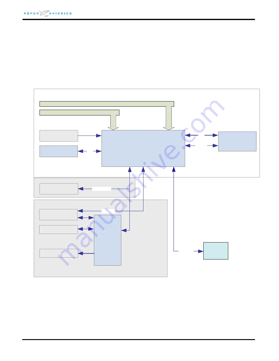
The system architecture in Figure 3-2 shows the relationships of the EFD1000 E5 with its
associated RSM, Configuration Module and optional ACU and EA100.
Figure 3-1: EFD1000 E5 System Architecture
EFD1000 E5
Flight Display
Existing Aircraft Pitot Line
Existing Aircraft Static Line
Digital GPS/VLOC
ARINC429
SPI
I2C
Analog
Converter Unit
(ACU, ACU2)
Analog NAV Source
AutoPilot
Configuration Module
Remote Sensor
Module (RSM)
RS-232
Legacy GPS
RS232
Aircraft Power
Analog GPS/VLOC via ACU
Digital GPS/VLOC
EA100
Autopilot
AHRS
Ethernet