background image

4


Operation 

28 

STERRAD VELOCITY Reader User’s Guide


9

Note: 

If the second positive control BI result is negative:

1.  Consult the “Troubleshooting” section (Chapter 8) of the User’s Guide.
2.  Contact Advanced Sterilization Products, Inc. (ASP).

The reader will ask for confirmation that the instructions are understood. Touch 

Yes

 or remove the BI to continue to Result Confirmation. In Result Confirmation, view 

the Result Summary by touching 

View and Print Result Summary

. Touch 

OK

 or remove 

the BI from the well to return to the Status Screen. Touching 

View and Print Result 

Summary

 opens the Result Summary page. If a printer is connected to the reader, touch 

Print

 on the lower left to print the Result Summary. Touch 

Add Note

 to leave notes 

about this specific result. Touch 

Done

 or remove the BI to return to Result Confirmation.

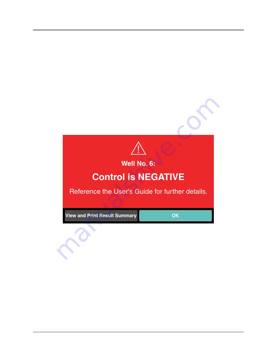
Figure 22. 

Second Negative Result on a Positive Control

Optional Visual Interpretation of Results

The reader generates results based on fluorescence only and DOES NOT read 

the visual color results. Visual interpretation is optional and should only be used for 
frequent monitoring when the reader is not available.

Summary of Contents for Sterrad Velocity Reader

Page 1: ...User s Guide AB11321031 AB11321031 50 January 2021 ASP 2021 All rights reserved Reader...

Page 2: ...VELOCITY ASP ACCESS and ALLClear are trademarks of Advanced Sterilization Products Inc ASP STERRAD and STERRAD NX are registered trademarks of Advanced Sterilization Products Inc ASP Other products me...

Page 3: ...10 Start and Warm up 10 The Status Screen 11 System Status Indicator 12 Biological Indicators 12 Biological Indicator Wells 13 Sleep Mode 14 Touch Screen 14 Barcode Scanner 14 Power Adapter 14 Chapte...

Page 4: ...7 Access Levels and Administrator Tasks 37 Access Levels 37 Utilities Menu 38 Admin Login 38 Manage Administrators 39 Add New Account 39 Edit or Delete Existing Account 39 Manage Sterilizers 39 Add Ne...

Page 5: ...s and Additional Parts 59 Appendix B Reader Specifications 61 Appendix C User s Network Connection Information 63 Appendix D Compliance and Regulatory Standards 65 Appendix E First Time Setup 67 Netwo...

Page 6: ...vi STERRAD VELOCITY Reader User s Guide THIS PAGE INTENTIONALLY LEFT BLANK...

Page 7: ...Safety Information explains personal safety as well as device safety information Operation explains how to operate the reader and obtain optimal results Maintenance explains how to clean and care for...

Page 8: ...rganism The reader incubates the BI at 57 C 134 6 F and provides final fluorescent results within 15 minutes The presence or absence of the viable indicator organism indicated by fluorescence in the B...

Page 9: ...out this User s Guide This information is for your safety and to ensure that you receive the most benefit from the safe operation of your reader Symbols Emits laser radiation Avoid direct eye exposure...

Page 10: ...ce manufacturer Date of Manufacture Indicates the date when the medical device was manufactured Hot Surfaces ASP The Netherlands BV BIC 1 5657 BX Eindhoven The Netherlands Authorized representative in...

Page 11: ...printed in boldface text Warnings indicate events or conditions that can result in serious injury or death Cautions indicate events or conditions that can result in damage to the reader or data loss I...

Page 12: ...or gloved hand or insert any non BI item in the instrument wells WARNING AVOID EXPOSURE TO ULTRAVIOLET LIGHT The fluorescence detection system uses an ultraviolet light source located inside the read...

Page 13: ...ASP ACCESS to prevent errors occurring during manual entry Process the BI according to the directions provided in the BI IFU Do not process a BI from a canceled or aborted sterilization cycle The accu...

Page 14: ...8 STERRAD VELOCITY Reader User s Guide THIS PAGE INTENTIONALLY LEFT BLANK...

Page 15: ...or Process Challenge Device test wells which can be used for test samples or positive controls The thermoplastic exterior makes the instrument easy to clean and maintain The built in barcode scanner c...

Page 16: ...r sets of interchangeable prongs which fit plug types A C G and I Attach the set of prongs which fit the plug socket to the AC power adapter Place the reader on a non vibrating level surface which is...

Page 17: ...indicate success After a BI is added to a well and the reading process has begun a series of small tick marks will appear around the well number The small tick marks indicate the elapsed time since t...

Page 18: ...d System Status System Failure Solid Red System Status General System Error Table 1 System Status Indicator Biological Indicators The BI is a single use testing device used to monitor the effectivenes...

Page 19: ...ts with the growth medium causing it to fluoresce under ultraviolet light Each well contains an ultraviolet light source to excite fluorescence in the growth medium and a photodetector to detect that...

Page 20: ...LEDs for illumination and aiming making it possible to scan a barcode in a wide variety of lighting conditions In order to scan a BI barcode hold the BI approximately 10 cm 4 in from the scanner with...

Page 21: ...tes Warm up When initially powered on the reader will display a splash screen and then go through a diagnostic and warm up sequence which takes up to 15 minutes After completing the warm up sequence t...

Page 22: ...e reader The Reader is also able to use a handheld barcode scanner attached to a USB port Hold the biological indicator 10 cm 4 in from the scanner with the barcode facing the scanner Align the barcod...

Page 23: ...p has remained red pink refer to the Chemical Indicator Result section Chapter 4 for more detailed instructions Touch Next to continue If the color has changed to yellow touch Yellow and refer to the...

Page 24: ...Touch Activated once complete Figure 8 Activate the BI Place the BI in the selected well immediately after activation An audible beep and a brief teal circle on the well indicator number will confirm...

Page 25: ...cal indicators that have been exposed to hydrogen peroxide please wear the appropriate PPE chemical resistant latex PVC vinyl or nitrile gloves Refer to the glove manufacturer s instructions for use f...

Page 26: ...the Chemical Indicator Result section Chapter 4 for a more detailed explanation If the color has not changed touch Red Pink and refer to the Troubleshooting section of this guide Chapter 8 Figure 12 C...

Page 27: ...rrect Touch No to return to the previous screen 9 Note Ensure that the time is synchronized between the reader and the Sterilizer to proceed to the next screen Figure 13 Manual Entry of Cycle Informat...

Page 28: ...l circle on the well indicator number will confirm placement in the well The reader will detect that the BI has been placed in the well and will begin the countdown until the result is displayed Figur...

Page 29: ...ing each result Chemical Indicator Result Read the chemical indicator CI result by comparing the CI color against the CI of an unprocessed BI The CI shifts from red pink unprocessed to yellow processe...

Page 30: ...ave notes about this specific result Touch Done or remove the BI to return to Result Confirmation Figure 18 Negative Test Result Positive Test Result A positive result for a test BI will be accompanie...

Page 31: ...tion that the instructions have been viewed Touch Yes or remove the BI to continue to the Result Confirmation Touch No to return to the previous screen In Result Confirmation view the result summary b...

Page 32: ...page If a printer is connected to the reader touch Print on the lower left to print the Result Summary Touch Add Note to leave notes about this specific result Touch Done or remove the BI to return t...

Page 33: ...n Touch an open well indicator or place the second positive control BI in an open well The reader will ask to confirm that a second positive control is being added Touch No to go to the Status Screen...

Page 34: ...OK or remove the BI from the well to return to the Status Screen Touching View and Print Result Summary opens the Result Summary page If a printer is connected to the reader touch Print on the lower l...

Page 35: ...ellow to confirm that the BI has been exposed to hydrogen peroxide Incubate the test BI and a positive control at 55 60 C 131 140 F for 5 to 7 days After incubation inspect the growth medium in the pr...

Page 36: ...30 STERRAD VELOCITY Reader User s Guide THIS PAGE INTENTIONALLY LEFT BLANK...

Page 37: ...erature well status barcode scanner status and software version System Information System Name Serial Number Model Number Manufacturer Date of Manufacture System Status Well Temperature Number of Well...

Page 38: ...ystem Information System Serial Number Software Version Corresponding Control Information Date Time Completed Lot Number Serial Number Result STERRAD Cycle Information STERRAD ID Cycle Type Cycle Numb...

Page 39: ...de 33 Reader Log The Reader Log is a software diagnostic log file available to users with administrator access It contains a log of software error codes which can be used to diagnose an issue with the...

Page 40: ...34 STERRAD VELOCITY Reader User s Guide THIS PAGE INTENTIONALLY LEFT BLANK...

Page 41: ...n abrasive detergent Do not spray cleaning products directly on the reader Do not attempt to clean or service the interior of the reader The interior of the reader contains no user serviceable parts a...

Page 42: ...cycler or disposed of in a local landfill Disposal of electronic circuit boards and coin cell batteries is regulated by the U S Environmental Protection Agency and most international environmental age...

Page 43: ...access Operator level access permits a user to perform tasks associated with the daily operation of the reader These privileges allow an operator to Select start and cancel a reading Scan the BI and...

Page 44: ...r privileges view and print past results perform diagnostic tests and update the software The following is a step by step explanation of the Utilities Menu and its functions Figure 23 Utilities Menu A...

Page 45: ...ngth The password must be eight to twelve characters in length with at least one uppercase letter one lowercase letter and one number Touching a text field brings up the on screen keyboard Typing text...

Page 46: ...odify the settings and touch Save Edits to save the changes Cancel returns to the previous screen Select an existing STERRAD and touch Delete to open the Delete Confirmation screen Touch Yes to confir...

Page 47: ...4 System Configuration Utility Language Selection Language Selection allows the operator to select the language displayed on the reader software Use the drop down menu to select the most appropriate l...

Page 48: ...of the reader Touch USB to use an external barcode scanner connected through a USB port Please note that when the external barcode scanner is enabled the internal barcode scanner will be disabled Read...

Page 49: ...aphic location from the drop down menu IMPORTANT Ensure that the time is synchronized between the reader the Sterilizer and the ASP ACCESS to prevent errors occurring during manual entry Calibrate Ins...

Page 50: ...P ACCESS Configuration screen After returning to ASP ACCESS Configuration verify that the settings are correct and test the connection again If the test fails a second time refer to the Troubleshootin...

Page 51: ...ut that specific file Select the destination and touch the arrow button between the lists to copy the file to the new location Touch Done to return to the Utilities Menu Update Software Software updat...

Page 52: ...46 STERRAD VELOCITY Reader User s Guide THIS PAGE INTENTIONALLY LEFT BLANK...

Page 53: ...perform an insertion sensor calibration after the reader has completed its warm up sequence Refer to the Calibrate Insertion Sensor section Chapter 7 for more information You haven t finished filling...

Page 54: ...adding a test BI select Test before scanning the BI barcode If adding a positive control BI select Control and scan a BI which has not been exposed to a sterilization cycle or been previously process...

Page 55: ...d Do not touch or move BIs during incubation Remove BIs from wells and perform proximity calibration Move reader away from vibration sources Ensure BI was properly activated Our records indicate that...

Page 56: ...in well sensor blocked Remove BI from affected well and wait 10 seconds to clear Check and remove debris from the well if present Perform a well calibration if possible After waiting for any BI activ...

Page 57: ...r Reinsert the BI in the selected well Do not cancel the sequence Simply check the activation and follow on screen instructions A control biological indicator has not been incubated for this lot in th...

Page 58: ...Reinstall the power adapter in the back of the reader If the problem persists contact ASP System status indicator is solid red General System Error Unplug the power adapter from the back of the reade...

Page 59: ...or healthcare facility policy and procedures and reprocess the load with a new BI Per BI IFU inspect BI for cracked ampuole pior to processing Do not process cracked BI Contact ASP Failure to scan BI...

Page 60: ...non sterile instruments and notification of the clinician s Repeat the test with a second BI Check BI for any damage per IFU prior to use for cycle Ensure the BI is handled and activated properly Do...

Page 61: ...er checked by ASP and do not use the sterilizer until unit has been checked BI ampoule breaks during sterilization Ampoule defect Reprocess load with new BI Chemical indicator indicates exposure prior...

Page 62: ...of the reader and attempt to use the touch screen again Clean the screen If the problem persists contact ASP Reader will not connect to network Network down faulty cable improper settings Note ASP ACC...

Page 63: ...ue has occurred causing all incubating biological indicators to be void Please remove all biological indicators Vibration or turning of BIs while incubating Move reader away from any vibration source...

Page 64: ...instructions Contact ASP if you are presented with an error code Any BI s that were incubating at the time of the error are invalid and the load should be reprocessed with a new BI Call Your ASP Repr...

Page 65: ...es and Additional Parts STERRAD VELOCITY Reader Printer P N 43221 STERRAD VELOCITY BI Activator P N 43250 Handheld USB Barcode Scanner P N 10308 60W AC Power Adapter Input 100V 240V AC at 50Hz 60Hz Ou...

Page 66: ...THIS PAGE INTENTIONALLY LEFT BLANK 60 STERRAD VELOCITY Reader User s Guide...

Page 67: ...t 30 C 86 F to 70 at 40 C 104 F non condensing Ambient Operating Pressure 103 kPa to 70 kPa 1 02 atm to 0 69 atm Ambient Operating Altitude 3 000 m to 100 m 9843 to 328 60W AC Power Adapter Input 100V...

Page 68: ...THIS PAGE INTENTIONALLY LEFT BLANK 62 STERRAD VELOCITY Reader User s Guide...

Page 69: ...erify the network connection While the connection is verified an animation will appear which says One Moment Verifying Connection A successful network connection test will display a green circle with...

Page 70: ...THIS PAGE INTENTIONALLY LEFT BLANK 64 STERRAD VELOCITY Reader User s Guide...

Page 71: ...30 EU Waste Electrical and Electronic Equipment WEEE Directive 2012 19 EU 47 CFR Part 15 FCC Part 15 Subpart B Class A IEC EN 61010 1 2010 CAN CSA C22 2 No 61010 1 12 2012 IEC EN 61010 2 010 2014 CAN...

Page 72: ...THIS PAGE INTENTIONALLY LEFT BLANK 66 STERRAD VELOCITY Reader User s Guide...

Page 73: ...Network Setup screen select the mode for connecting to the network Auto will retrieve the network connection information from the network and Manual will allow the user to enter the network connectio...

Page 74: ...te a Pairing Code Enter the ASP ACCESS Username and Pairing Code and touch Test to verify the connection The reader will show a loading screen with the message One Moment Verifying Connection while it...

Page 75: ...tup Set the date time and time zone for the current geographic location Choose the date and time format to be displayed on the reader Touch Back to go to the previous screen or touch Next to continue...

Page 76: ...administrator account Touch Back to return to the previous screen Figure 30 Administrator Setup Once the initial administrator account is created add more administrator accounts by touching Add New M...

Page 77: ...information populates the drop down menus for manual cycle entry Sterilizers added to the system appear in a table Add more sterilizers by touching Add New To edit or delete existing sterilizers touch...

Page 78: ...I color change for a control BI Otherwise touch No Touch Next to continue or touch Back to return to the previous screen Printer Setup A printer can be attached via a USB port if desired Attach the pr...

Page 79: ...e the Documentation and all other information provided to you in relation to the Software constitutes confidential information of ASP and you shall not disclose any such information without the expres...

Page 80: ...OR PURSUANT TO THIS LICENSE AGREEMENT SHALL EXCEED IN THE AGGREGATE THE PRICE PAID BY YOU FOR THE PRODUCT Subject to binding arbitration provided hereinbelow this License as well as any claim related...

Page 81: ...tration Act however any party will have 30 days to appeal the award by notifying the arbitration organization and all parties in writing The originally selected arbitration organization will appoint a...

Page 82: ...use sources of hydrogen peroxide other than Certified ASP Hydrogen Peroxide containers cassettes in the Product Further your use of the Software in any non compliant manner with the License may subje...

Reviews: